
Automatic control system for an electrosurgical generator

an electrosurgical generator and control system technology, applied in the field of electrosurgical generators, can solve the problems of unplanned power delivery or undesired duration of power delivery to the surgical site, surgeons also experience difficulty in repeating and/or consistently desiccating tissue to the desired level, and the modified goertzel algorithm proposed by banks does not provide the real and imaginary frequency components of the sampled waveform

Active Publication Date: 2007-11-27
COVIDIEN AG
View PDF587 Cites 698 Cited by
  • Summary
  • Abstract
  • Description
  • Claims
  • Application Information

AI Technical Summary

Benefits of technology

The system ensures precise and consistent power delivery to the surgical site by calculating the phase difference between voltage and current waveforms, providing feedback for tissue impedance and type, and enabling adjustments to achieve desired tissue desiccation levels with reduced computational steps and enhanced accuracy.

Problems solved by technology

Unfortunately, that technique often leads to unintended power delivery or undesired duration of power delivery to the surgical site.
Surgeons also experience difficulty in repeatably and / or consistently desiccating tissue to the desired levels due to the user's reaction time and / or machine response time when manual or foot activated switches are used for manual control.
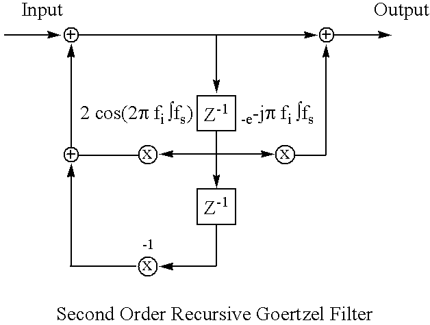
An N-point DFT is computationally demanding, but will calculate the real and imaginary frequency terms for all the frequencies up to half the sampling rate of the signal.
However, the modified Goertzel algorithm proposed by Banks does not provide the real and imaginary frequency components of the sampled waveform.
As a result, the modified Goertzel algorithm is unsuited for determining the phase of the waveform.

Method used


Image

  • Automatic control system for an electrosurgical generator
  • Automatic control system for an electrosurgical generator
  • Automatic control system for an electrosurgical generator

Examples


Embodiment Construction

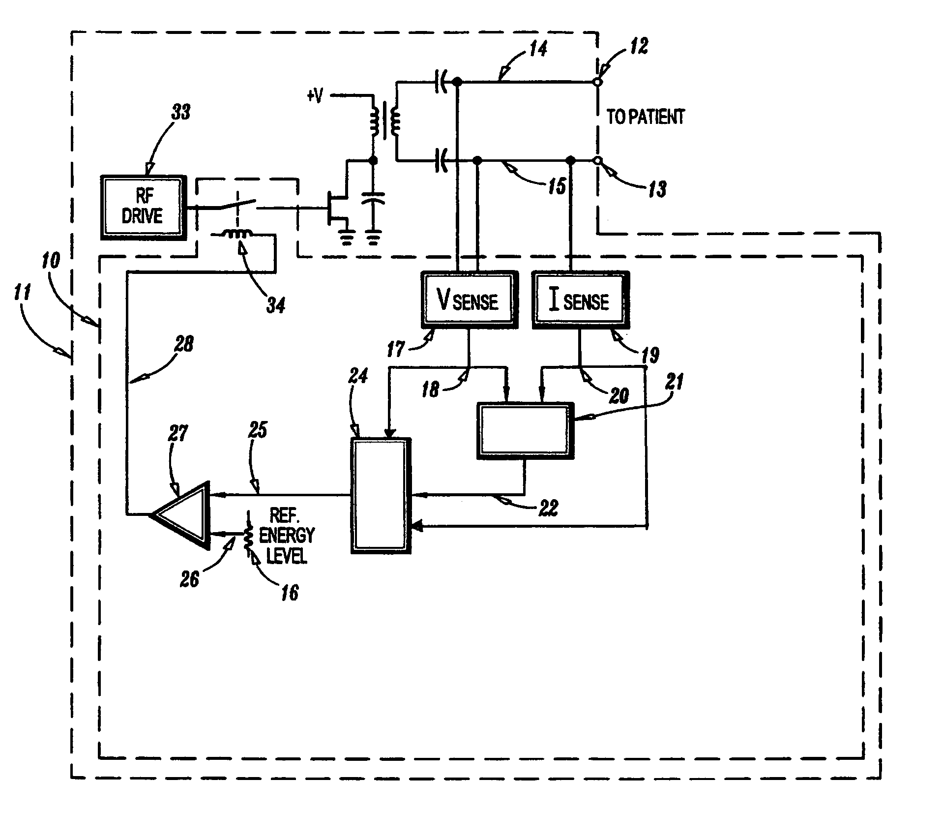
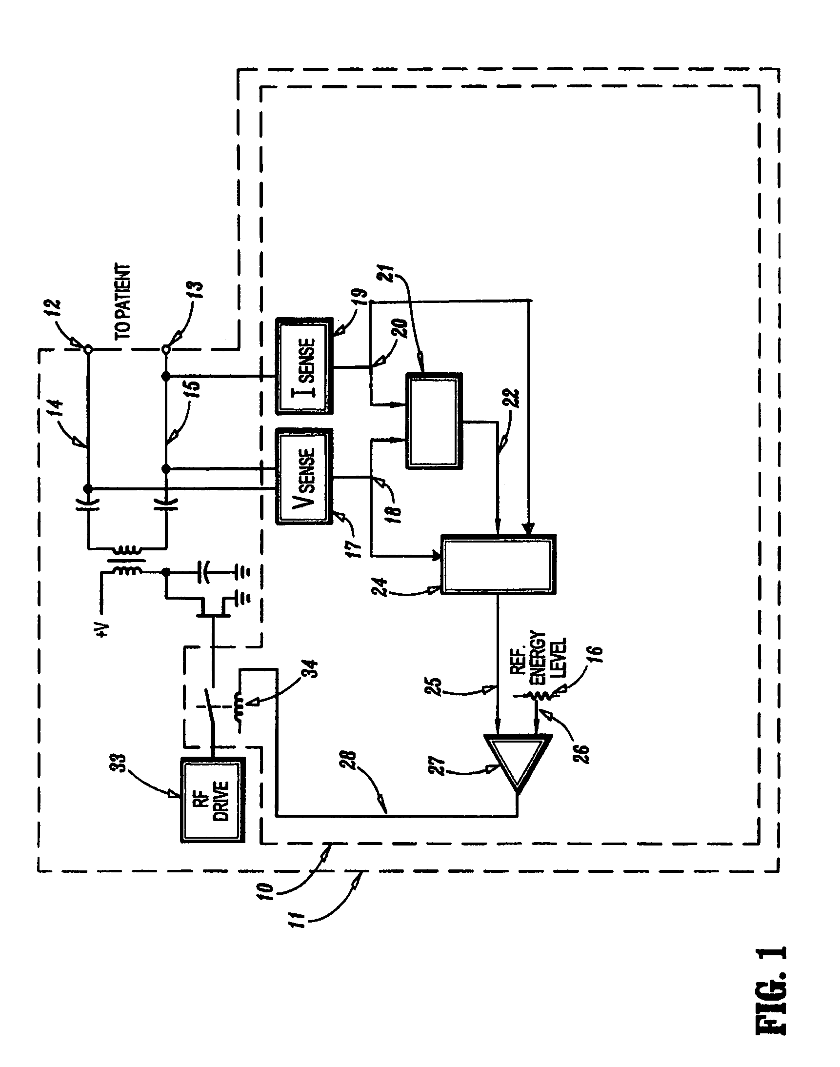
[0018]Embodiments of the presently disclosed automatic control system will now be described in detail with reference to the drawing where, in FIG. 1, an exemplary embodiment of the presently disclosed automatic control system 10 is illustrated. Automatic control system 10 is ideally disposed within an electrosurgical generator 11. Electrosurgical generator 11 includes a user control 16 preferably on its front panel accessible to the doctor for setting the output level desired for a particular electrosurgical procedure. User control 16 may be a knob, a slider, or other structures and / or devices as is known in the art for use by the doctor to set a reference signal 26 indicative of the desired output.

[0019]A voltage sensing circuit 17 has an isolation transformer, which acts as an inductive pickup. Its primary side is electrically connected between leads 14 and 15 for inducing a voltage signal 18 on the secondary windings thereby responding to the high frequency electrosurgical energy...


PUM


Abstract

An automatic control system for an electrosurgical generator is herein disclosed. The automatic control system includes voltage and current sensing circuits, a processing circuit, an output determining circuit, and a control circuit. Samples of the voltage and current outputs are supplied to the processing circuit and the output determining circuit to generate an output signal. The output signal is compared to a reference signal to generate a feedback signal for controlling a drive circuit.

Description

CROSS REFERENCE TO RELATED APPLICATIONS:[0001]This application claims the benefit of U.S. Provisional Application No. 60 / 515,816, filed Oct. 30, 2003.BACKGROUND OF THE INVENTION[0002]1. Technical Field[0003]The present disclosure relates to electrosurgery. More particularly, the present disclosure relates to an automatic control system for an electrosurgical generator.[0004]2. Background of Related Art[0005]Surgeons have tried to deal with energy application by adjusting the basic power level of the electrosurgical generator and using a hand or foot switch to control the power applied over time. Unfortunately, that technique often leads to unintended power delivery or undesired duration of power delivery to the surgical site. Surgeons also experience difficulty in repeatably and / or consistently desiccating tissue to the desired levels due to the user's reaction time and / or machine response time when manual or foot activated switches are used for manual control. In addition, during e...

Claims


Application Information

Patent Timeline
Patent Type & Authority Patents(United States)
IPC IPC(8): A61B18/18A61B18/12
CPCA61B18/1206A61B2018/00875A61B2018/00755A61B2018/00642
Inventor WHAM, ROBERT H.STURM, THOMAS A.
Owner COVIDIEN AG
Learn More