Liquid crystal display device, image display device, illumination device and emitter used therefore, driving method of liquid crystal display device, driving method of illumination device, and driving method of emitter

a technology of liquid crystal display device and emitter, which is applied in the direction of instruments, computing, electric digital data processing, etc., can solve the problems of short life of emitters, poor image quality, and image persistence or image bleeding, and achieve shortening the life of emitters, suppressing the influence of electromagnetic waves, and achieving display quality.

Inactive Publication Date: 2006-01-03
SHARP KK
View PDF51 Cites 50 Cited by
  • Summary
  • Abstract
  • Description
  • Claims
  • Application Information

AI Technical Summary

Benefits of technology

[0016]The present invention was made in view of the foregoing problems and it is an object of the present invention to provide a liquid crystal display device, an emitter, and an emitter driving method, all capable of realizing a desirable display quality also in a fast-moving image, while suppressing shortening of life of emitters in an illuminating section and reducing influence of electromagnetic waves.
[0017]Another object of the present invention is to provide a liquid crystal display device, a driving method of a liquid crystal display device, and an illumination device, for relieving a coloring phenomenon on image contours, which is caused when the emitters of the illuminating section are controlled to include a certain OFF period or dimming period per one vertical period.
[0018]Yet another object of the present invention is to provide an image display device, an illumination device, and a driving method of an illumination device, all capable of illuminating each emitting area with a pulse time width which is practically and sufficiently short, so as to improve display quality by eliminating image persistence in a fast-moving image.

Problems solved by technology

One of the problems of liquid crystal display devices, which have been conventionally used as display screens of, for example, lap-top personal computers or word processors, is that a poor image quality results by such a phenomenon as image persistence or image bleeding when displaying a fast-moving image.
Such application of a rectangular wave to the emitter causes the following problems.
That is, because the applied waveform is a rectangular wave, the emitter has a short life, which is problematic in actual application.
For example, when a voltage of a rectangular wave is applied to a common cold cathode tube of a liquid crystal display device, a current flows abruptly through the cold cathode tube at a rise of emission, whereas the current is suddenly shut down in the cold cathode tube at a fall of emission, which may result in a reverse current flow.
Such a current behavior is detrimental to life of the cold cathode tube.
Further, since the rectangular wave include a high harmonic component, the problem of electromagnetic radiation is posed.
This causes the coloring phenomenon on image contours in a display of a fast-moving image in particular, thus lowering display quality.
Such a cooling / heating cycle damages the cold cathode tube and shortens its life.
It is therefore difficult to maintain the environmental temperature of the cold cathode tube constant.
A failure to maintain a constant environmental temperature of the cold cathode tube results in decrease in temperature itself, and luminance is lowered as a result.
However, when an image is displayed using the foregoing illuminating section, the following problems are posed.
Thus, the conventional structure fails to improve display quality with a short pulse time width, and the effect of shortening the pulse width time becomes weak.
(1) By the repeated ON and OFF of the emitter at the frame frequency, the emitter is damaged and the life of the emitter becomes short as a result.
(2) By the presence of the OFF period, display luminance is lowered significantly.

Method used


Image

  • Liquid crystal display device, image display device, illumination device and emitter used therefore, driving method of liquid crystal display device, driving method of illumination device, and driving method of emitter
  • Liquid crystal display device, image display device, illumination device and emitter used therefore, driving method of liquid crystal display device, driving method of illumination device, and driving method of emitter
  • Liquid crystal display device, image display device, illumination device and emitter used therefore, driving method of liquid crystal display device, driving method of illumination device, and driving method of emitter

Examples


first embodiment

[0108][First Embodiment]

[0109]The following will describe one embodiment of the present invention referring to FIG. 1 through FIG. 3.

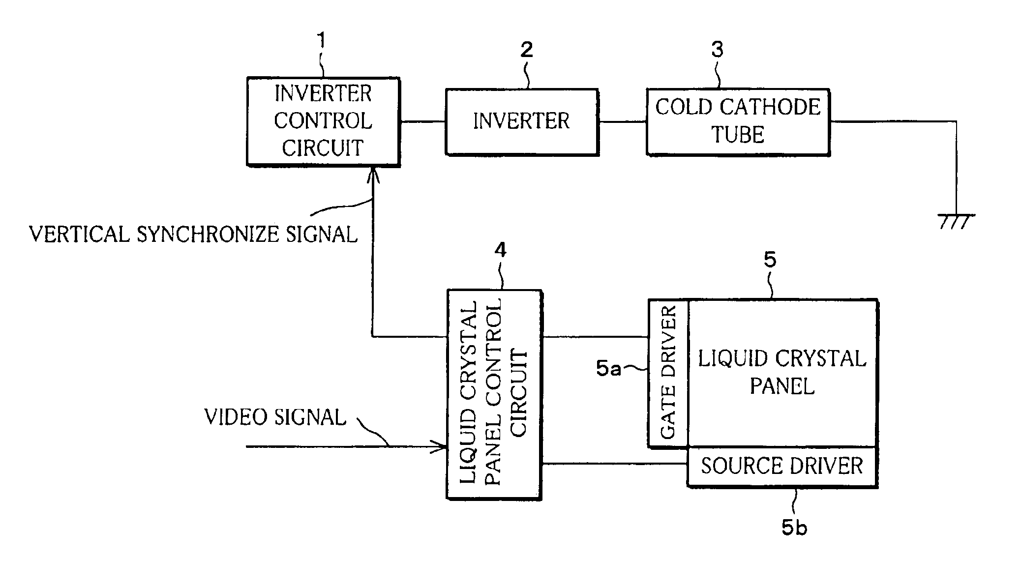
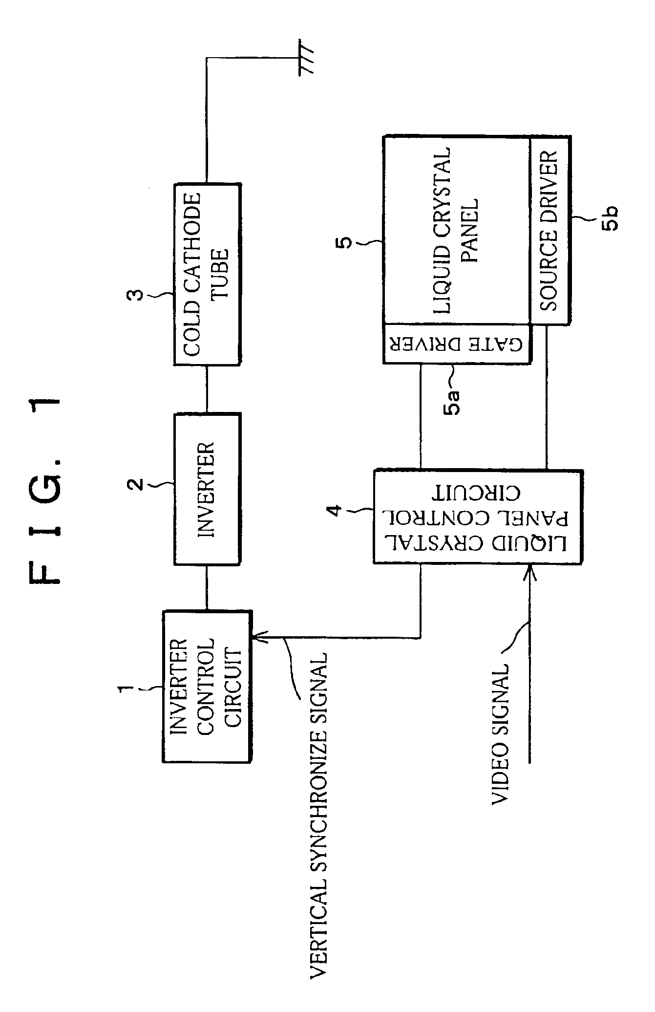
[0110]A liquid crystal display device (active-matrix liquid crystal display device) according to the present embodiment chiefly includes, as shown in FIG. 1, an inverter control circuit 1, an inverter 2, a cold cathode tube 3 (emitter), a liquid crystal panel control circuit 4, and a liquid crystal panel 5.

[0111]The inverter control circuit 1 receives a vertical synchronize signal which is outputted from the liquid crystal panel control circuit 4, and outputs an inverter driving signal for driving the inverter 2 to the inverter 2. The inverter 2 applies to the cold cathode tube 3 (white cold cathode tube) a high voltage whose frequency is varied according to the inverter driving signal. The cold cathode tube 3, upon receiving the high voltage, emits light to illuminate the liquid crystal panel 5.

[0112]The liquid crystal panel control circuit 4, upon in...

second embodiment

[0171][Second Embodiment]

[0172]The following will describe another embodiment of the present invention referring to FIG. 9 through FIG. 15.

[0173]First, the mechanism of a coloring phenomenon, in which contours of an image are colored in fast-moving images is explained with reference to FIG. 14 and FIG. 15.

[0174]A liquid crystal display device (active-matrix liquid crystal display device) as shown in FIG. 14 is chiefly made up of an inverter control circuit 501, an inverter 502, a cold cathode tube 503 (emitter), a liquid crystal panel control circuit 504, and a liquid crystal panel 505.

[0175]The inverter control circuit 501 receives a vertical synchronize signal which is inputted from the liquid crystal panel control circuit 504, and outputs driving signals for driving the inverter 502 to the inverter 502. The inverter 502 applies a high voltage whose frequency is varied according to the driving signal to the cold cathode tube 503. The cold cathode tube 503, upon receiving the high ...

third embodiment

[0257][Third Embodiment]

[0258]The following will describe yet another embodiment of the present invention with reference to FIG. 26 through FIG. 31.

[0259]As shown in FIG. 26, a liquid crystal display device 601 as an image display device according to the present embodiment adopts, for example, an active-matrix mode with TFTs (thin film transistors) of 640×480 dots. A liquid crystal panel (display section) 605 as an image panel includes liquid crystal display elements (pixels) (not shown), which are a plurality of display elements making up a screen, for modulating a light transmission state of a liquid crystal according to image data which are applied while being scanned. The liquid crystal display elements seal, for example, a twist-nematic liquid crystal therein. The liquid crystal panel 605 includes a gate driver 603 for driving scanning lines in the liquid crystal panel 605, and a source driver 604 for driving signal lines. The liquid crystal display device 601 includes a liquid...


PUM


Abstract

A cold cathode tube for illuminating pixels with light which is in accordance with an output signal has luminance which gradually increases at a rise and gradually decreases at a fall per one frame time. In certain example embodiments, illuminating elements respectively illuminate display elements in such a manner that each illuminating element group respectively illuminates a display element group in a second luminance in a period from Time P to Time (P+tb), and illuminates in a first luminance in a period from the Time (P+tb) to Time (P+f), the second luminance being darker than the first luminance, where tb is a predetermined time, f is one vertical period, and the Time P is a time at which a display element band having an earliest scanning time in the display element group the illuminating element group illuminates is scanned.

Description

FIELD OF THE INVENTION[0001]The present invention relates to a liquid crystal display device which displays information by illuminating display elements, an image display device, and an illumination device and an emitter used therefor, and also relates to a driving method of the liquid crystal display device, a driving method of the illumination device, and a driving method of the emitter.BACKGROUND OF THE INVENTION[0002]One of the problems of liquid crystal display devices, which have been conventionally used as display screens of, for example, lap-top personal computers or word processors, is that a poor image quality results by such a phenomenon as image persistence or image bleeding when displaying a fast-moving image.[0003]In view of this drawback, WO95 / 01701 (published date: Jan. 12, 1995) (Tokuhyohei 8-500915), Japanese Publication for Unexamined Patent Publication No. 082019 / 1989 (published date: Mar. 28, 1989) (Tokukaisho 64-082019), and Japanese Publication for Unexamined ...

Claims


Application Information

Patent Timeline
Patent Type & Authority Patents(United States)
IPC IPC(8): G09G3/24G02F1/133G02F1/1335G02F1/13357G09G3/34G09G3/36G09G5/00
CPCG09G3/3413G09G3/342G09G2310/024G09G2310/066G09G2330/06G09G2320/0242G09G2320/0261G09G2320/0633G09G2320/064G09G2310/08G02F1/133
Inventor MIYACHI, KOICHIJINDA, AKIHITOSHIOMI, MAKOTO
Owner SHARP KK
Why Eureka
Try Eureka