Eureka AIR delivers breakthrough ideas for toughest innovation challenges, trusted by R&D personnel around the world.

Electronic equipment and operation control method for electronic equipment

a technology of electronic equipment and operation control, applied in the field of electronic equipment, can solve the problems of useless operation keys relating to timer functions

Inactive Publication Date: 2006-01-10
SONY CORP
View PDF8 Cites 16 Cited by
  • Summary
  • Abstract
  • Description
  • Claims
  • Application Information

AI Technical Summary

Benefits of technology

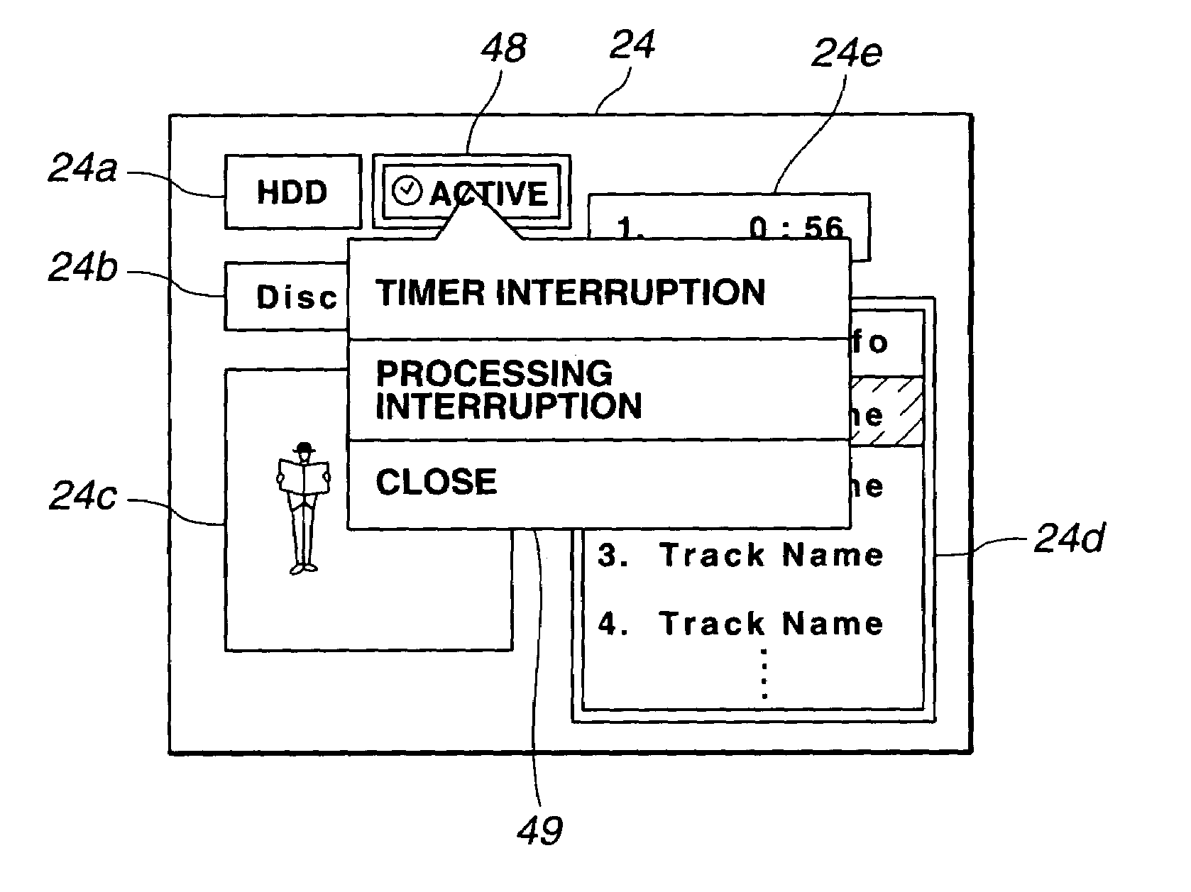
[0007]In addition, in accordance with this invention, there is provided an operation control method for an electronic equipment permitted to undergo operation control on the basis of timer reservation by user, the method including a setting step of setting time designated by user, an operation control step of controlling operation of the electronic equipment in accordance with the set time, a display control step of controlling display means so that specific display is carried out when the electronic equipment is operative, a designation detection step of detecting designation of user with respect to the specific display, and a step such that when designation of user is detected at the designation detection step, control is conducted such that the set time is neglected and operation of the electronic equipment when designation of user is detected is continued.

Problems solved by technology

However, for users who do not utilize such timer function, operation keys relating to timer function would be useless.
In addition, when there are useless operation keys, this constitutes the cause of confusion of user in carrying out various operations.

Method used


Image

  • Electronic equipment and operation control method for electronic equipment
  • Electronic equipment and operation control method for electronic equipment
  • Electronic equipment and operation control method for electronic equipment

Examples


Embodiment Construction

[0017]Explanation will now be given with reference to the attached drawings in connection with an electronic equipment and an operation control method for an electronic equipment according to this invention.

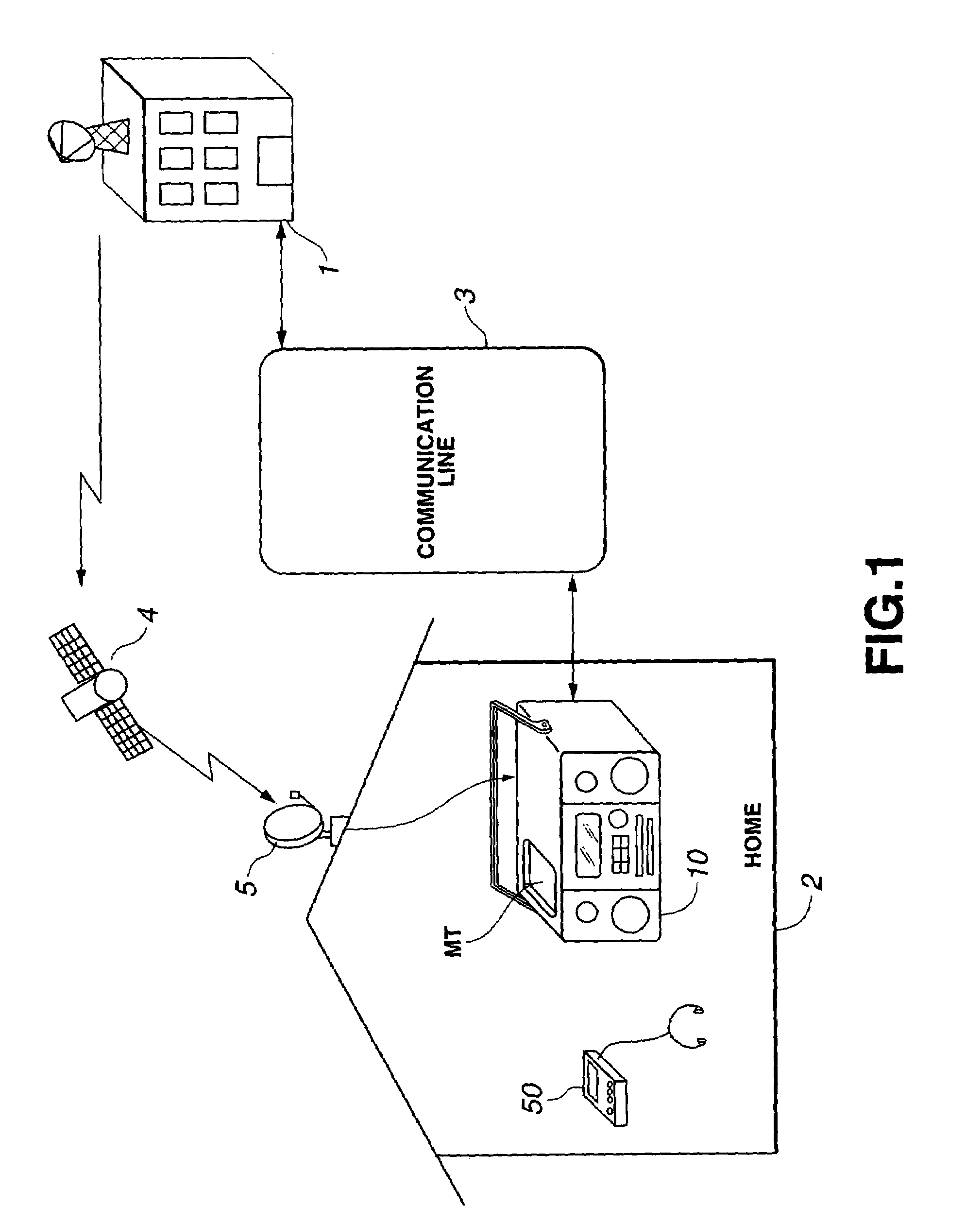
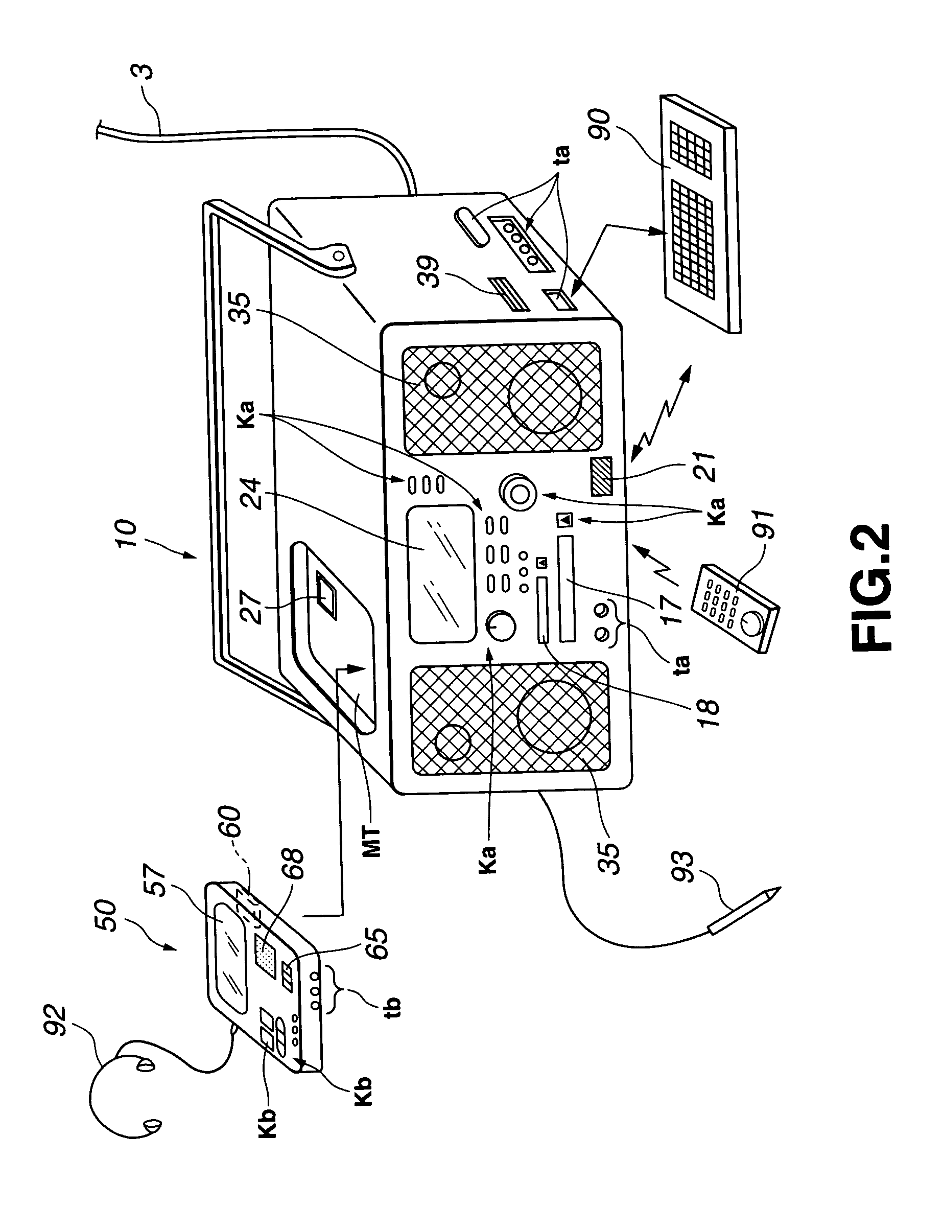
[0018]FIG. 1 is a model view showing outline of information delivery system to which this invention is applied. This information delivery system is essentially composed of a recording / reproducing apparatus (unit) 10 that general user uses in home 2, etc., and an information center 1 as information service organization for providing information used in the recording / reproducing unit 10.

[0019]The information center 1 and the recording / reproducing unit 10 carry out communication of various information through a communication line 3. The communication line 3 is comprised of, e.g., public line network such as ISDN line, etc. or dedicated line network constructed exclusively for such system, and the form of the line is not specifically limited. In addition, information communication be...


PUM

PropertyMeasurementUnit
timeaaaaaaaaaa
current timeaaaaaaaaaa
start timeaaaaaaaaaa

Abstract

An electronic unit that is permitted to undergo operation control on the basis of a timer reservation set by a user includes a setting section for setting a time designated by the user, an operation control section for controlling the operation of the electronic unit in accordance with time set by the setting section, a display section for displaying an operation portion for operating the electronic unit, a display control section such that when the electronic unit is operative in accordance with the operation control section, it controls the display section so that a specific display is carried out on the display section, and a designation detecting section for detecting a designation of the user with respect to the specific display, whereby when a designation of the user is detected by the designation detecting section, the operation control section conducts a control to neglect the time set by the setting section and to continue the operation of the electronic unit when the designation of the user is detected.

Description

TECHNICAL FIELD[0001]This invention relates to an electronic equipment and an operation control method therefor which can carry out operation control by timer.BACKGROUND ART[0002]In recent years, audio equipments having timer function have been known. This timer function is, e.g., function to allow power supply of the equipment to be turned ON or OFF at timer designation time such as start time and / or end time, etc. that user has set in advance. Moreover, this timer function is function to execute operation such as receiving operation of broadcasting program by tuner and / or reproduction of CD (Compact Disc), etc. at time that user has set. Namely, by employing an approach to allow user to make setting such that, e.g. tuner is turned ON at start time which is timer designation time, such a control is carried out that tuner is operative when current time measured by the timer function reaches start time. Accordingly, user can set, e.g., rising scheduled time as start time to utilize t...

Claims


Application Information

Patent Timeline
Patent Type & Authority Patents(United States)
IPC IPC(8): G08B1/00G11B31/00G06F3/048G06F3/0481G06F3/0482G06F3/0488G11B19/08G11B19/16
CPCG11B19/16G11B19/08G11B2220/2537G11B2220/2525G11B2220/2508
Inventor TANAKA, IZURU
Owner SONY CORP
Why Eureka
Eureka Blog
Learn More