Method of operating a dispensing cabinet

Inactive Publication Date: 2006-01-10
OMNICELL
View PDF26 Cites 116 Cited by
  • Summary
  • Abstract
  • Description
  • Claims
  • Application Information

AI Technical Summary

Problems solved by technology

The prior art typically relies upon the illumination of an LED, which may be difficult to spot in a large bank of cabinets or may be overlooked if there is more than one LED on any particular drawer or compartment.

Method used


Image

  • Method of operating a dispensing cabinet
  • Method of operating a dispensing cabinet
  • Method of operating a dispensing cabinet

Examples


Embodiment Construction

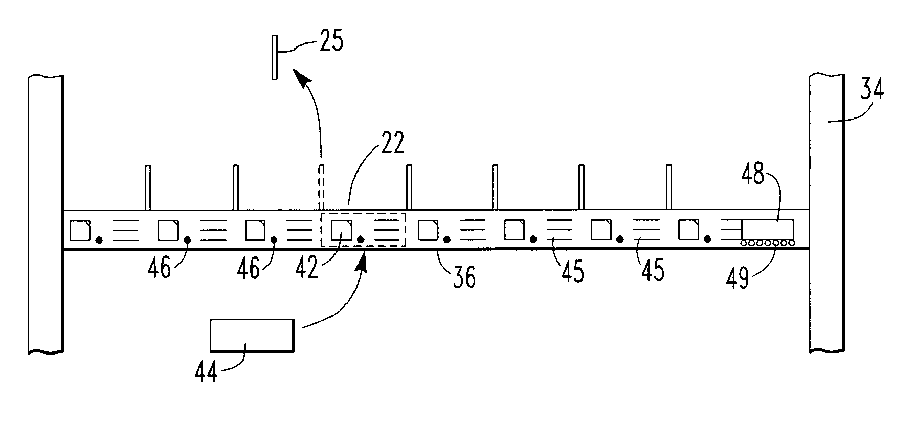
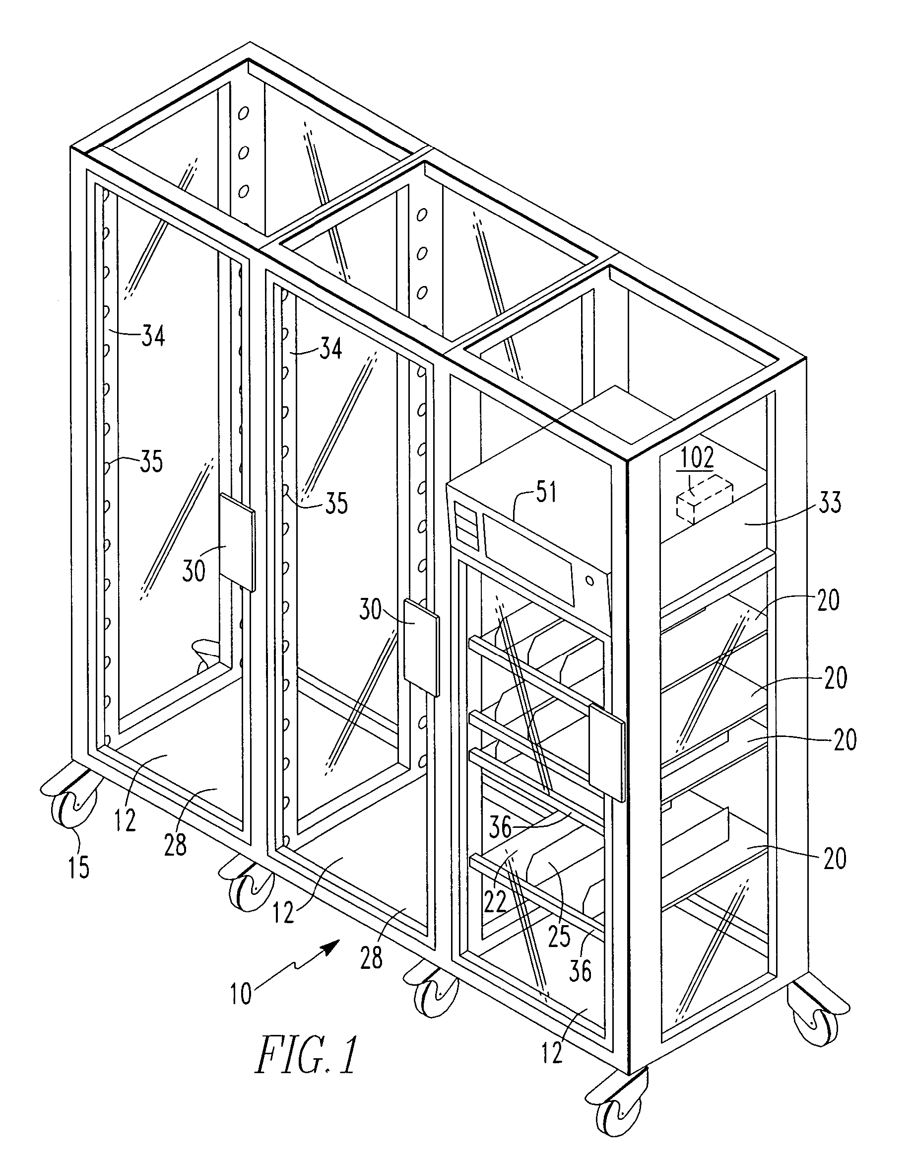
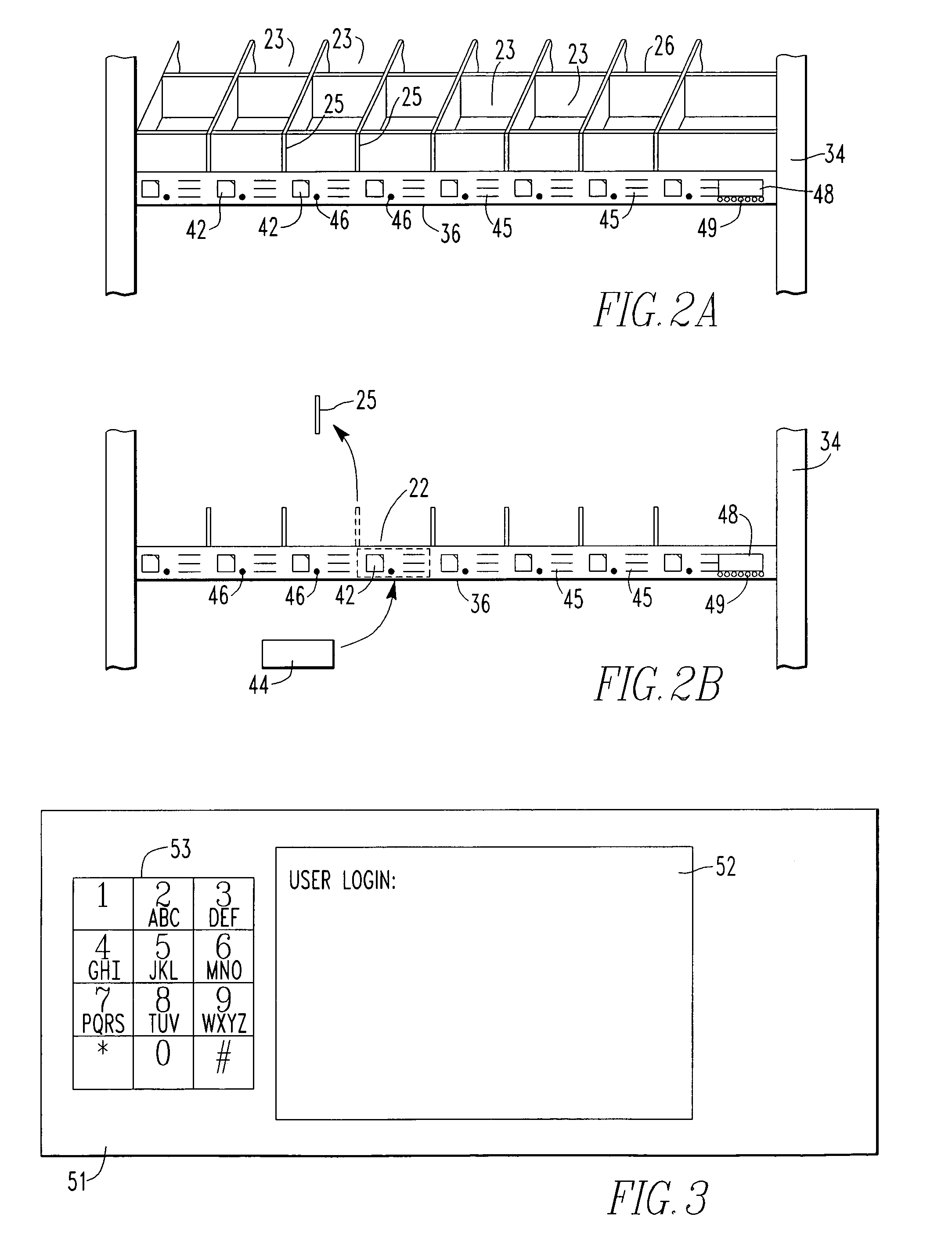
[0023]FIG. 1 illustrates a dispensing unit 10 of the type on which the methods of the present invention may be practiced. Although the dispensing unit 10 is discussed in an environment in which medications and / or medical supplies are dispensed, other types of items may be dispensed. As shown in FIG. 1, the dispensing unit 10 is comprised of several (usually three to five) vertical cabinets 12 each optionally having wheels or casters 15. The cabinets 12 are divided by a number of shelves 20. Each shelf 20 may be subdivided into a number of individual compartments 22 by vertical dividers 25 carried by the shelves 20. Additionally, as shown in FIG. 2A, horizontal dividers 26, which run perpendicular to the vertical dividers 25, may be provided to divide a shelve 20 into a matrix of small individual compartments 23. The shelves 20 and dividers 25, 26 are individually movable (or removable) so that the height and width of the compartments 22, and the height, width and depth of compartmen...


PUM


Abstract

A method of operating a dispensing cabinet to identify the locations where items to be dispensed are located is comprised of a login step in which user information is entered into a processor controlling the dispensing cabinet. The processor unlocks certain doors of the dispensing cabinet in response to the user information. Assuming that a locate mode of operation has been chosen, the locations of the items to be located are determined by the processor. An alpha-numeric display positioned on a shelf within the cabinet begins flashing with the number of items to be located that are held by that shelf. After the user identifies the shelves having flashing alpha-numeric displays, the user may enter a dispense mode or may logoff causing the unlocked doors to lock.

Description

CROSS-REFERENCE TO RELATED APPLICATIONS[0001]The present invention is a divisional of U.S. application Ser. No. 10 / 010,387 entitled “Method of Operating a Dispensing Cabinet” filed 7 Dec. 2001 now U.S. Pat. No. 6,895,304 and having common ownership.BACKGROUND OF THE INVENTION[0002]1. Field of the Invention[0003]The present invention relates to methods for dispensing items and more particularly, to methods of dispensing medications and supplies from a medication / medical supply cabinet.[0004]2. Description of the Background[0005]A wide variety of systems are used in medical facilities for the dispensing and inventory of medications and medical supplies. For example, U.S. Pat. No. 5,520,450 discloses a supply station with an internal computer. The supply station is comprised of a cabinet having a plurality of lockable doors. Information is provided to a computer which unlocks the doors causing the doors to open slightly. To aid the user in selecting the appropriate compartment, the inf...

Claims


Application Information

Patent Timeline
Patent Type & Authority Patents(United States)
IPC IPC(8): G07F17/00A61G12/00A61J7/00G07F5/26G07F11/62G07F17/12
CPCG07F5/26G07F17/12G07F17/0092G07F11/62A61G12/001
Inventor SPANO, JR., PHILIP H.MEEK, JR., ROBERT B.
Owner OMNICELL
Why Eureka
Try Eureka