Supercharge Your Innovation With Domain-Expert AI Agents!

Automotive clamp accessory

a technology for automobiles and accessories, applied in forging/pressing/hammering equipment, manufacturing tools, forging/hammering/hammering machines, etc., can solve the problems of automobile bodywork damage, automobile collision damage, and all or part of the frame of the automobil

Inactive Publication Date: 2006-01-17
CONNER STEVEN G
View PDF9 Cites 6 Cited by
  • Summary
  • Abstract
  • Description
  • Claims
  • Application Information

AI Technical Summary

Benefits of technology

"The present invention is an automotive clamp accessory that can be used to pull on the rear edge or lip of a damaged vehicle's frame without having to remove bolted-on vehicle parts or attached glass. The accessory allows for proper straightening by pulling on the accessory with an external force. It includes a base member with a body bore for attaching to a pulling clamp and a pair of opposing pivot bores for mounting the pull clamp. The accessory also includes side walls that extend the length of the base member. The technical effect of this invention is that it provides a simple and efficient solution for straightening damaged vehicle frames without the need for additional parts or tools."

Problems solved by technology

Automotive accidents produce damage of varying severity to the involved vehicles.
In a relatively minor automobile accident of the “fenderbender” type, only the bodywork of the automobile is damaged.
In more severe accidents, all or part of the frame of the automobile can be bent, in addition to the bodywork panels.
A problem with the prior art method discussed above is that it is often required to remove bolted-on vehicle parts such as headlights, fenders, etc., or attached glass such as windshields, windows etc., in order for the pull clamp or sling to properly access or grab the frame.
Removing vehicle parts in order to ultimately access the damaged frame of the vehicle results in increased labor cost, as well as additional risk of windshield or window breakage and bodywork damage.

Method used


Image

  • Automotive clamp accessory
  • Automotive clamp accessory
  • Automotive clamp accessory

Examples


Embodiment Construction

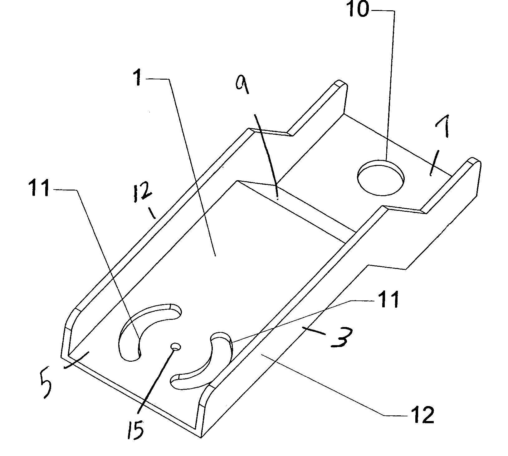
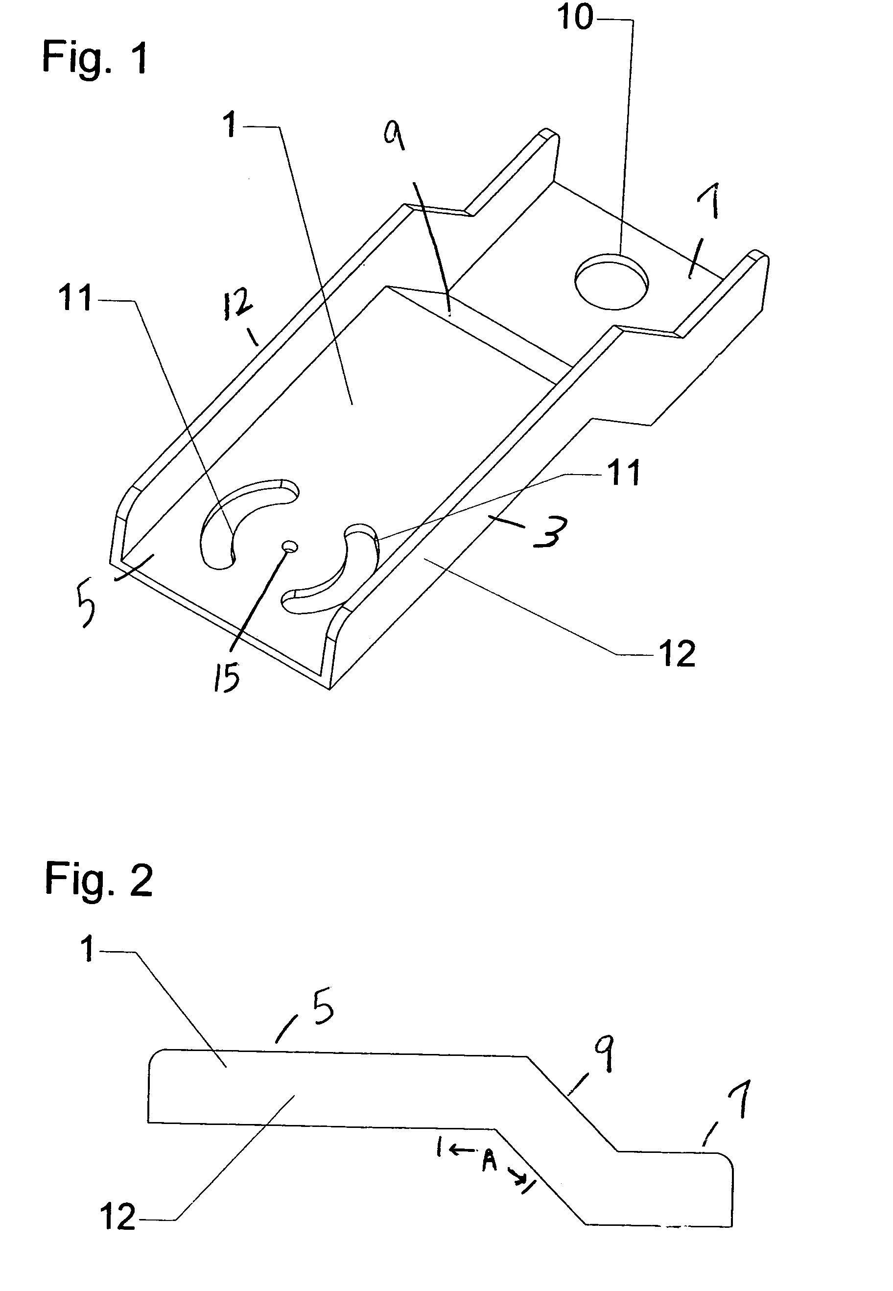
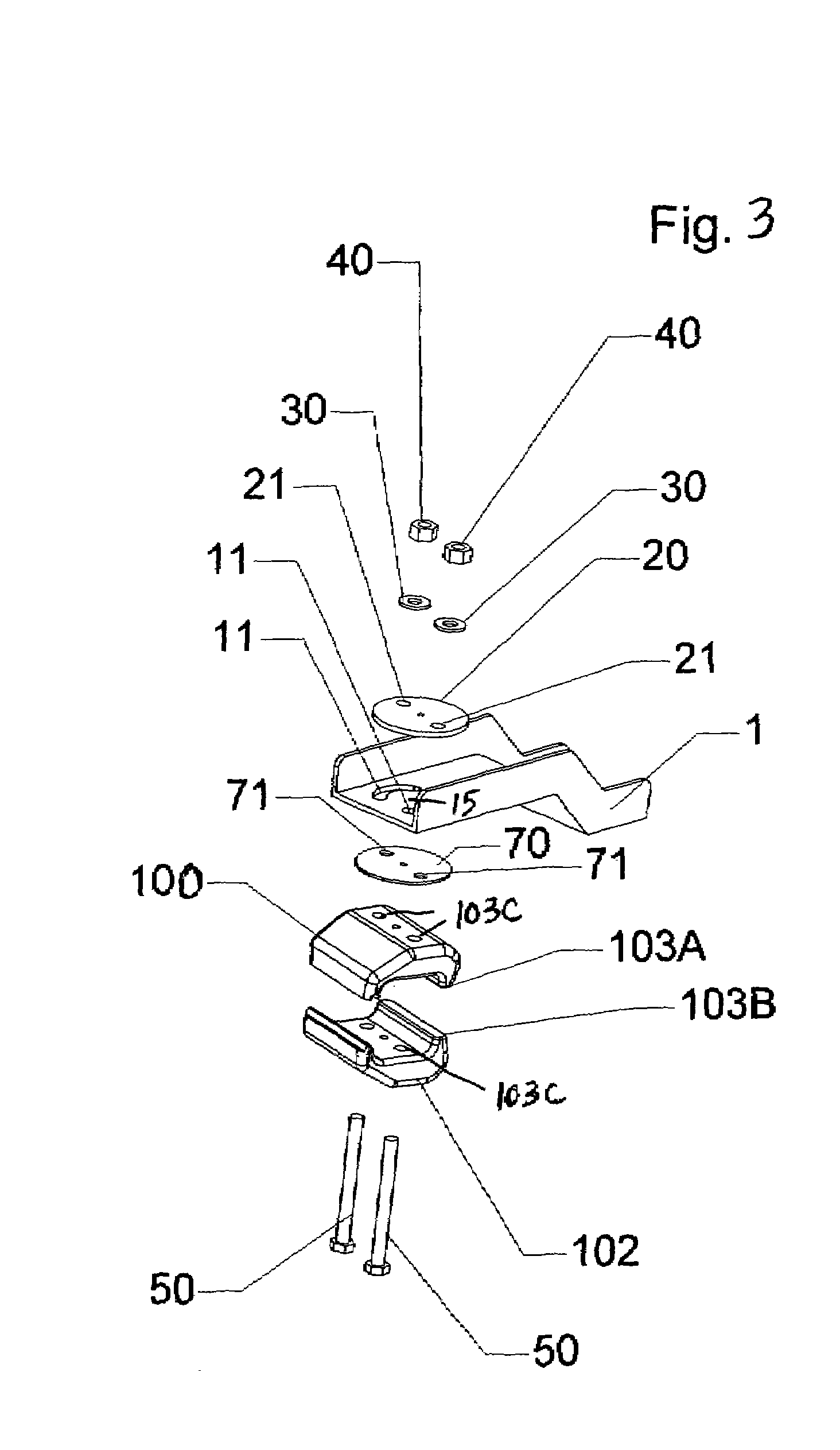
[0017]In accordance with the present invention, an automobile clamp accessory used when straightening a damaged vehicle's body or frame is disclosed. The automotive clamp accessory is directed to an automotive clamp accessory that can be used with existing prior art clamps to pull on the rear edge or lip of the post of panel of a damaged vehicle's frame. Once the prior art clamp is attached to the damaged portion of the vehicle frame and to the clamp accessory of the present invention, straightening is accomplished by pulling on the automotive clamp accessory with an external force to return the post or panel back to its original shape.

[0018]Specifically, it will be noted in the drawings that the automotive clamp accessory relates to an apparatus that allows a prior art pull clamp to grip the rear edge or lip of a damaged post or panel without first being required to remove bolted-on vehicle parts or attached glass in order for the pull clamp to properly access or grab the frame. In...


PUM

PropertyMeasurementUnit
angleaaaaaaaaaa
external forceaaaaaaaaaa
lengthaaaaaaaaaa

Abstract

An automotive clamp accessory that can be used with existing prior art clamps to pull on a damaged vehicle's frame. The clamp accessory can be attached to a variety of types of damaged vehicle frames and locations without first being required to remove bolted-on vehicle parts or attached glass in order for the pull clamp to properly access or grab the frame. Once the clamp accessory is attached, straightening is accomplished by pulling on the clamp accessory with an external force to return the frame back to its original shape. In the preferred embodiment, the clamp accessory includes a first end portion, a second end portion, and a wall disposed between the first and second ends that forms a “stair-step” configuration. The first end portion having a pair of opposing pivot bores for mounting the prior art pull clamp thereto. The pivot bores allow the pulling clamp to be tightened in selected positions for various straightening applications. In position, the clamp accessory passes over the damaged frame so that the body bore of the clamp accessory is aligned and on an axis with the clamp jaws of the pull clamp.

Description

CROSS REFERENCES TO RELATED APPLICATIONS[0001]U.S. Provisional Application for patent Ser. No. 60 / 532,744, filed Dec. 29, 2003, with title “Adjustable Automotive Clamp Accessory that Allows a Forward or Angled Pull on a Post or Panel that has a Lip on the Rear of the Post or Panel” which is hereby incorporated by reference. Applicant claims priority pursuant to 35 U.S.C. Par. 119(e)(i).[0002]Statement as to rights to inventions made under Federally sponsored research and development: Not ApplicableBACKGROUND OF THE INVENTION[0003]1. Field of the Invention[0004]The present invention relates generally to vehicle collision repair, in particular to the straightening of a damaged post or panel of the vehicle's body or frame. Specifically, the present invention is directed to a clamp accessory that can be used with existing prior art clamps to pull on a damaged vehicle's post or panel that has an edge, or lip disposed on the rear of the post or panel. Once the prior art clamp, and clamp a...

Claims


Application Information

Patent Timeline
Patent Type & Authority Patents(United States)
IPC IPC(8): B21J13/08B21D1/14B21D5/04
CPCB21D1/145Y10S72/705
Inventor CONNER, STEVEN G.
Owner CONNER STEVEN G
Features
  • R&D
  • Intellectual Property
  • Life Sciences
  • Materials
  • Tech Scout
  • Unparalleled Data Quality
  • Higher Quality Content
  • 60% Fewer Hallucinations
Learn More