
Apparatus and methods for providing an emergency lighting augmentation system

a technology of emergency lighting and apparatus, applied in the field of illumination, can solve problems such as power failure, brownout, power failure, etc., and achieve the effect of reducing the number of emergency lighting sources

Inactive Publication Date: 2006-01-17
CYBERLUX CORP
View PDF37 Cites 37 Cited by
  • Summary
  • Abstract
  • Description
  • Claims
  • Application Information

AI Technical Summary

Benefits of technology

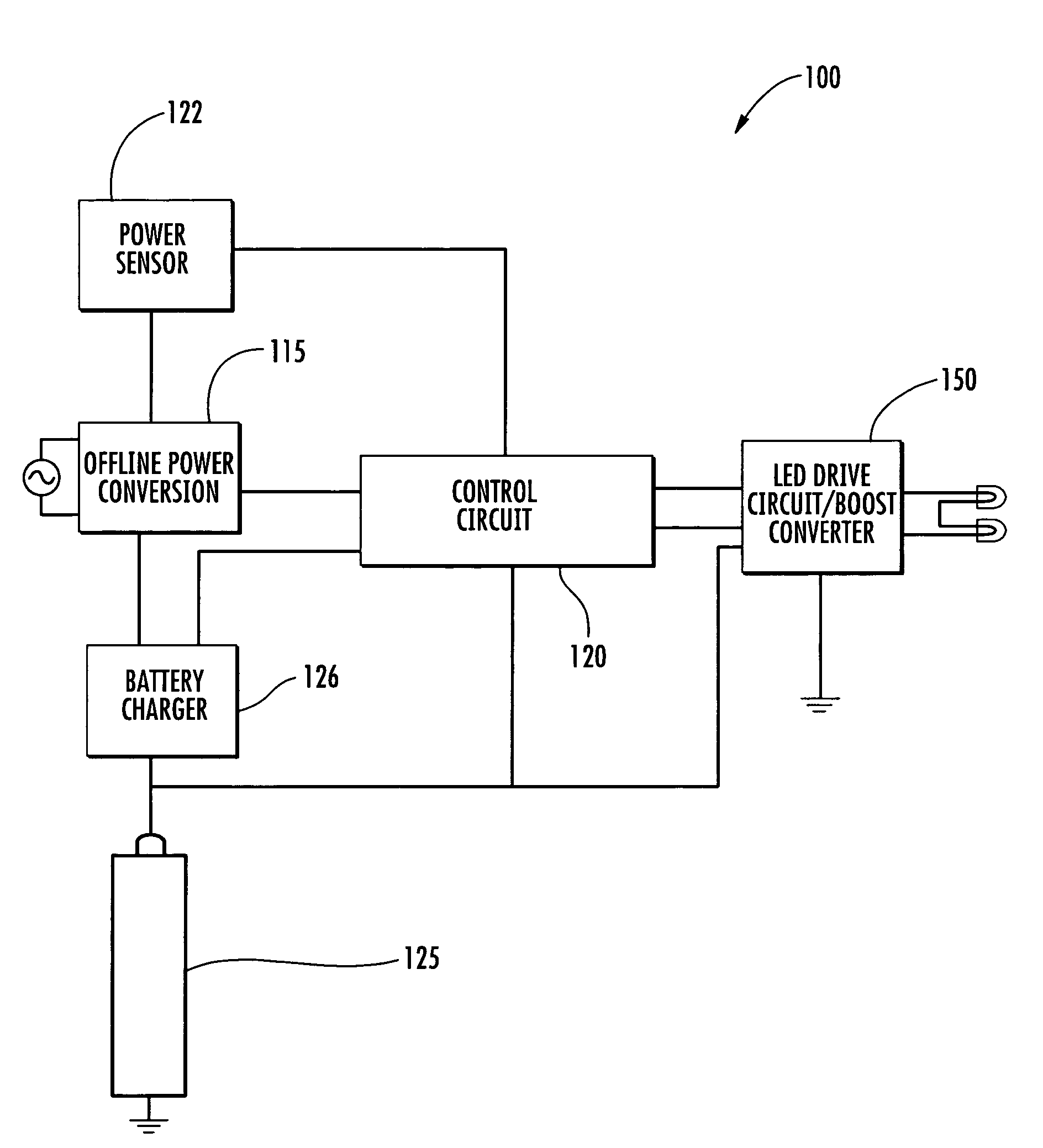
"The present invention is an emergency lighting device that uses LEDs, a battery, and a control circuit to turn existing light fixtures into emergency lighting systems. It includes a power sensor to activate the LEDs when power is lost, providing a wash of light over darkened areas. The technical effect is to provide a reliable and effective solution for ensuring safety and security in the event of power outages or other emergency situations."

Problems solved by technology

Periodically, homes, offices, public buildings, hospitals, industrial manufacturing facilities and the like, experience emergency situations which cause power failures leaving these buildings entirely without light.
Such power failures may result from electrical short circuits, brownouts, fire, accidents, natural disasters (i.e., floods, hurricanes, tornados, etc.) or a planned shutdown of electricity within a facility or dwelling.
Should these facilities remain without power, especially in the critical areas of these facilities (e.g., intensive care units of hospitals, exit hallways and stairwells generally, and the like) the public safety is placed at risk.
Unfortunately, however, most emergency-generated power outages last much longer than three hours.
Further, the need for effective lighting may not be realized until the disaster has abated.

Method used


Image

  • Apparatus and methods for providing an emergency lighting augmentation system
  • Apparatus and methods for providing an emergency lighting augmentation system
  • Apparatus and methods for providing an emergency lighting augmentation system

Examples


Embodiment Construction

[0021]The present invention now will be described more fully hereinafter with reference to the accompanying drawings, in which preferred embodiments of the invention are shown. This invention may, however, be embodied in many different forms and should not be construed as limited to the embodiments set forth herein; rather, these embodiments are provided so that this disclosure will be thorough and complete and will fully convey the scope of the invention to those skilled in the art. Like numbers refer to like elements throughout.

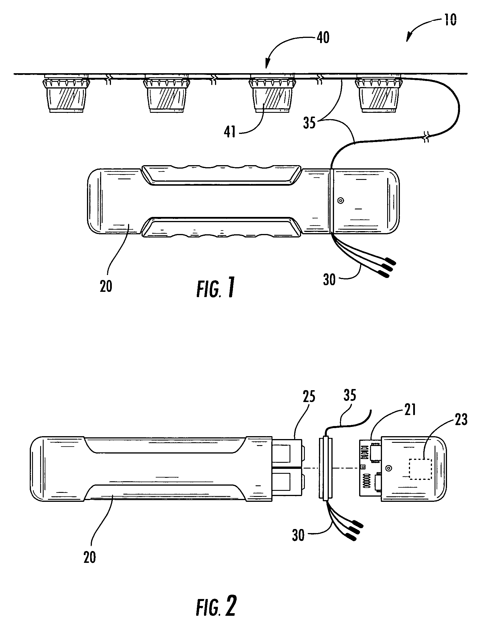
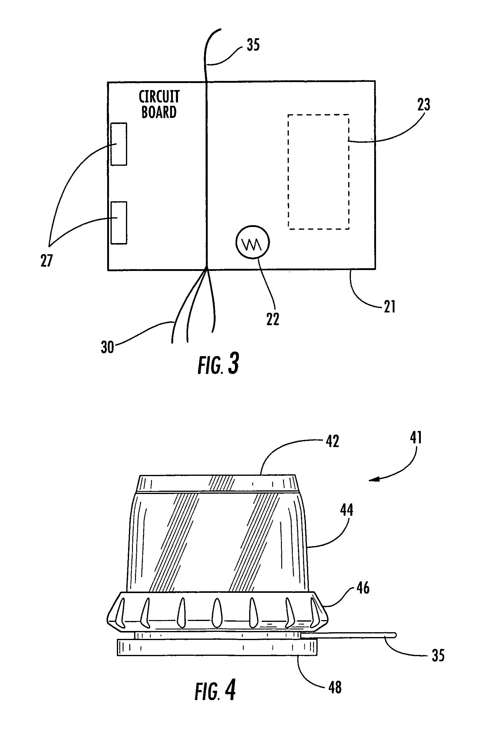
[0022]FIG. 1 depicts a perspective view of a lighting device in accordance with one embodiment of the present invention. According to the depicted embodiment, the emergency lighting device 10 structurally comprises, a main body housing 20, a power supply connector 30, an array of light emitting diodes 40 (LEDs) and a LED wire 35. In particular, electricity is channeled from the main body housing 20 to the LEDs 40 via a LED wire 35. Although depicted as incl...


PUM


Abstract

The present invention includes an emergency lighting device comprising, at least one light emitting diode (LED), a local energy source such as a lithium ion battery, a control circuit in electric communication with the at least one LED and further sensing a main power supply, and a reflector for broadcasting light produced by the LED to designated areas. In particular, the present invention transforms existing fluorescent, incandescent or halogen light fixtures into emergency lighting systems for homes, hospitals, hotels, nursing homes and businesses. The device includes a power sensor for triggering the control circuit to engage the LEDs when electrical service is disrupted, thereby broadcasting a wash of light over an otherwise darkened room or corridor.

Description

CROSS-REFERENCES TO RELATED APPLICATIONS[0001]This application claims the benefit of U.S. provisional patent application Ser. No. 60 / 510,915, filed Oct. 14, 2003, which is fully incorporated herein by reference.BACKGROUND OF THE INVENTION[0002]1) Field of the Invention[0003]The present invention relates generally to the field of illumination and, more particularly, the invention relates to a solid state lighting source such as a light-emitting diode (LED) device that provides prolonged emergency lighting in response to a power loss event.[0004]2) Description of Related Art[0005]Periodically, homes, offices, public buildings, hospitals, industrial manufacturing facilities and the like, experience emergency situations which cause power failures leaving these buildings entirely without light. Such power failures may result from electrical short circuits, brownouts, fire, accidents, natural disasters (i.e., floods, hurricanes, tornados, etc.) or a planned shutdown of electricity within ...

Claims


Application Information

Patent Timeline
Patent Type & Authority Patents(United States)
IPC IPC(8): F21V19/04F21S8/00F21S9/02F21V7/00F21V23/04H01R13/66H01R13/717H01R25/00H02J9/02H02J9/06H05B37/04
CPCF21S8/035F21V7/0008F21V23/04F21V23/0442H01R13/6683H01R13/717H01R13/7172H01R13/7175F21S9/022Y10S362/802F21Y2101/02F21Y2113/02H01R25/006H02J9/02Y10S362/80F21Y2113/20F21Y2115/10
Inventor EVANS, DONALD F.BRADY, ROBERT O.SCHMIDT, MARK D.
Owner CYBERLUX CORP
Learn More