

Ink jet recording apparatus
- Summary
- Abstract
- Description
- Claims
- Application Information
AI Technical Summary
Benefits of technology
Problems solved by technology
Method used
Image

Examples
first embodiment
[First Embodiment]
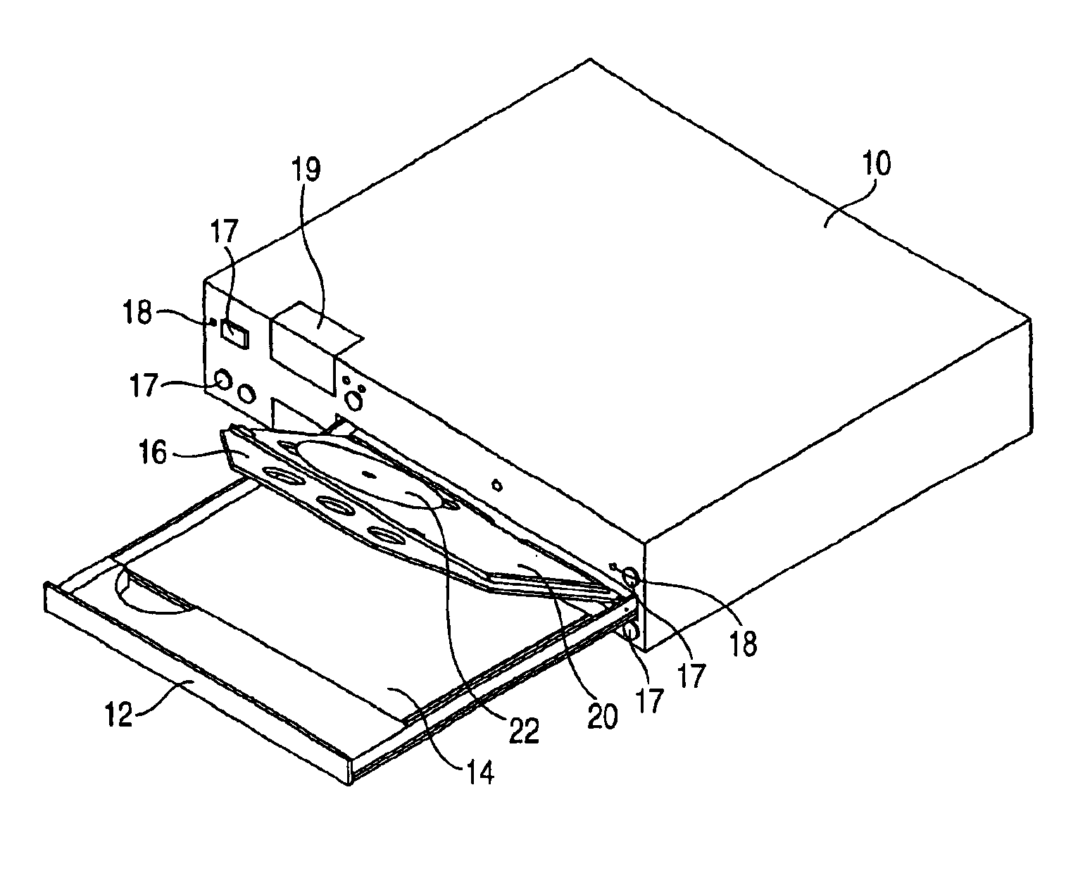
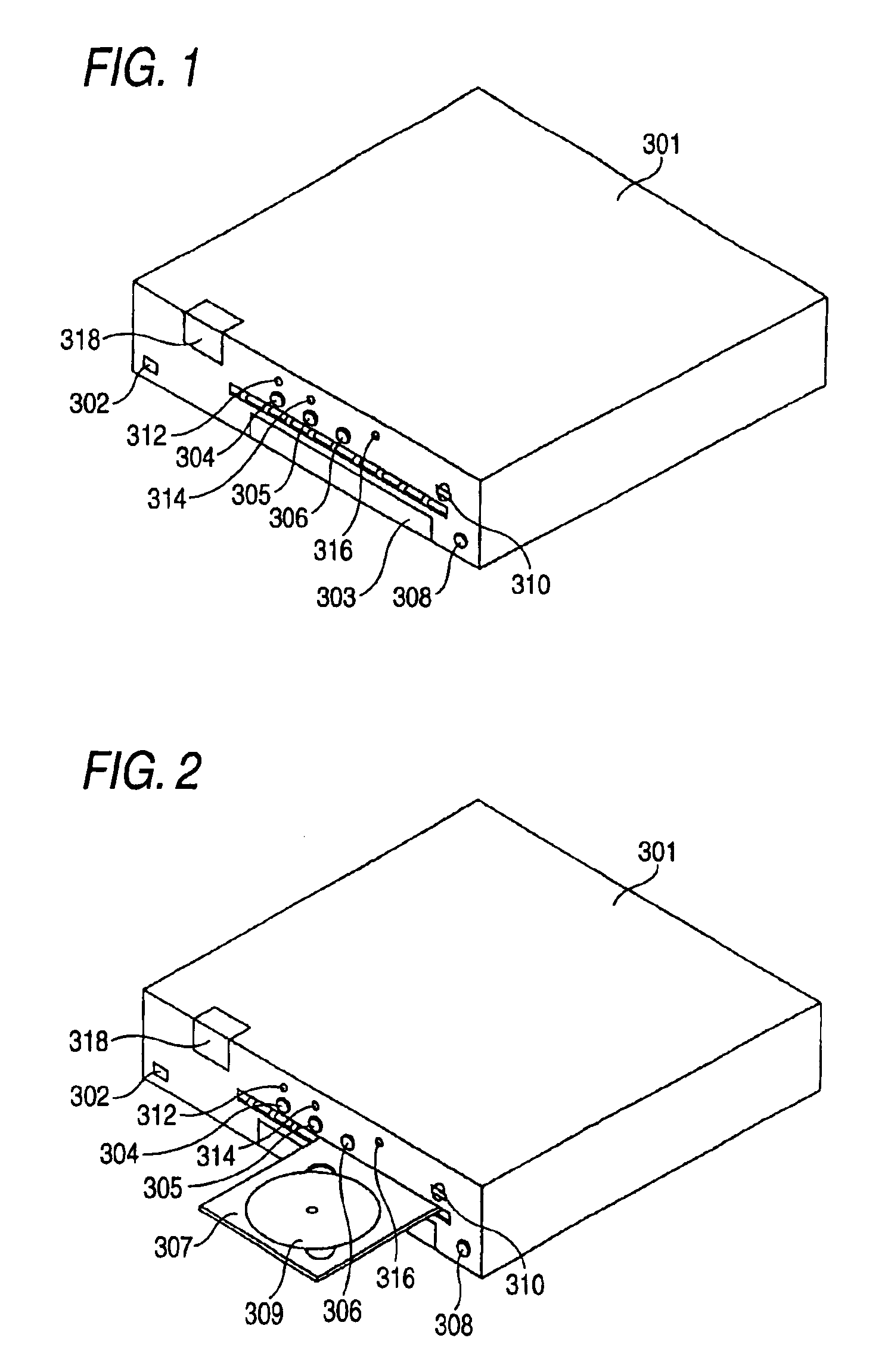
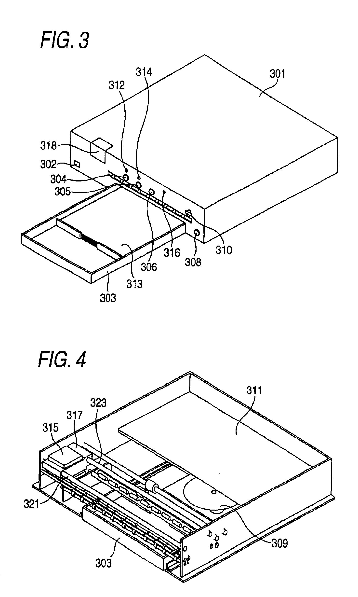
[0141]FIG. 1 is a perspective view showing an external appearance of an ink jet recording apparatus 301 which is an embodiment of the invention in a state that a sheet feed tray 303 and a disc tray 307 are accommodated in the recording device. FIG. 2 is a perspective view showing an external appearance of the ink jet recording apparatus 1 in a state that the disc tray 307 is protruded to outside the recording device (A position of the disc tray in this state will be referred to as a loading / unloading position). FIG. 3 is a perspective view showing an external appearance of the ink jet recording apparatus 1 in a state that a sheet feed tray 303 having a recording sheet 313 put thereon is drawn out to the full extent (A position of the sheet feed tray in this state will be referred to as “sheet-feed-tray maximum drawn-out position”, hereinafter). FIG. 4 is a perspective view showing a key portion of the ink jet recording apparatus 301.
[0142]Referring to FIGS. 1 throu...
PUM
 Abstract
Description
Claims
Application Information