
Recording medium playback device

a playback device and recording medium technology, applied in the field of recording medium playback devices, can solve the problems of failure of the playback device, difficulty in use, appearance impairment,

Inactive Publication Date: 2006-01-24
PIONEER CORP
View PDF8 Cites 9 Cited by
  • Summary
  • Abstract
  • Description
  • Claims
  • Application Information

AI Technical Summary

Benefits of technology

The present invention provides a playback device that is smaller in depth dimension, making it easier to install in a limited space. The device includes a recording medium accommodation unit for stacked recording mediums, a carriage chassis with a pickup, a turntable, and a pickup moving means for playing back the recording medium. The pickup moving means has a feed screw mechanism and a guide means to guide the pickup. The device also has a recording medium loading means for inserting recording mediums from outside. When the carriage chassis is in a standby position, the pickup is positioned on a vertical tangential plane that is tangent to the outer edge of the recording medium on the carriage chassis side. The device also includes a stopper portion for abutting against the outer edge of the recording medium. The technical effects of the invention are reduced size of the playback device and improved installation flexibility.

Problems solved by technology

If the playback device a is mounted in the instrument panel in such a condition, the differences in the depth dimension between the playback device a and other devices mounted vertically above or below the playback device a cause steps to be formed between the protruding front panel of the playback device a and those of the other devices, making them difficult to use or impairing the appearance.
Further, a gap between the playback device a and the accommodation space of the instrument panel caused by the protruding front panel will likely allow dirt or dust to enter into the interior of the playback device a, leading to a failure of the playback device a.

Method used


Image

  • Recording medium playback device
  • Recording medium playback device
  • Recording medium playback device

Examples


Embodiment Construction

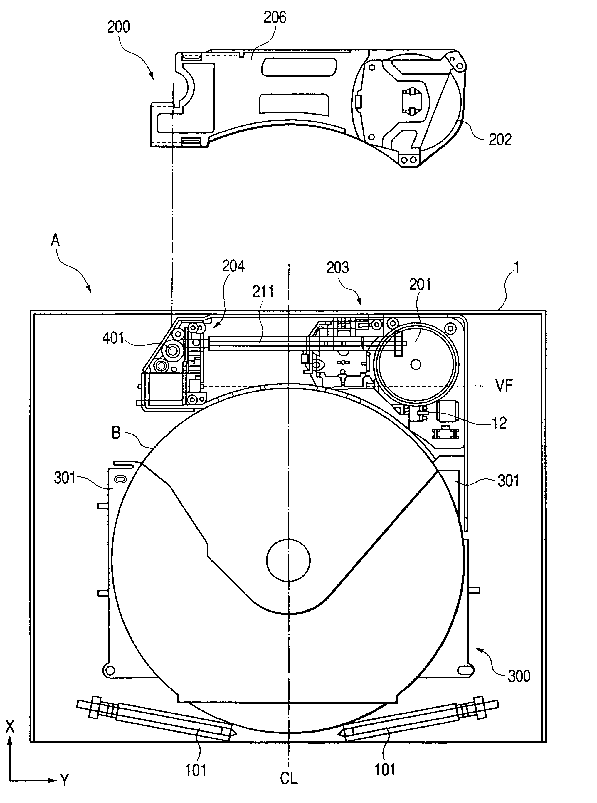
[0039]Embodiments of the playback device applying the present invention will be described in detail by referring to FIGS. 1 through 13. In these drawings, too, the direction in which to load the recording medium B is taken as an X direction, the direction in which to clamp the recording medium B is taken as a Z direction, and the direction perpendicular to the X and Z directions is taken as a Y direction.

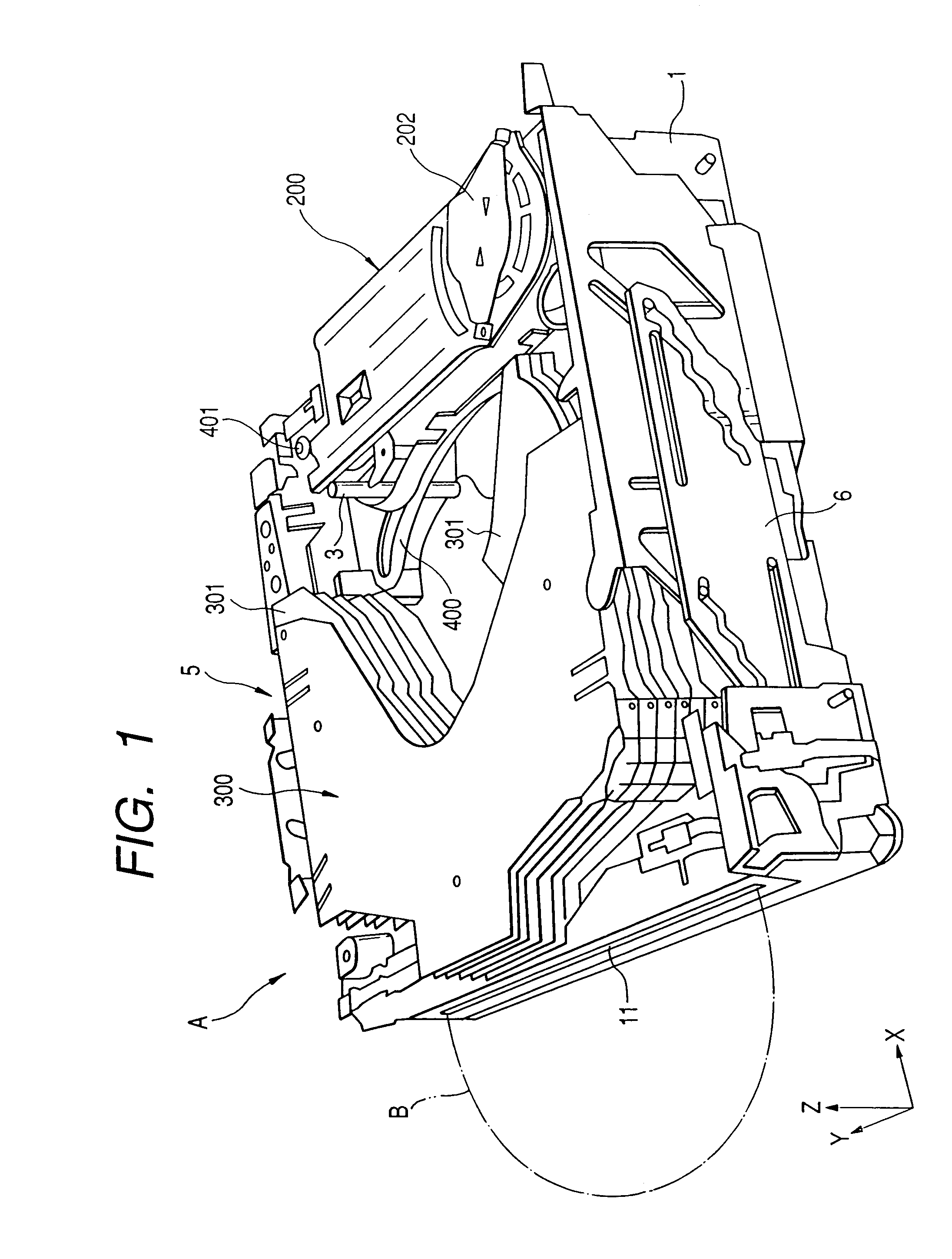
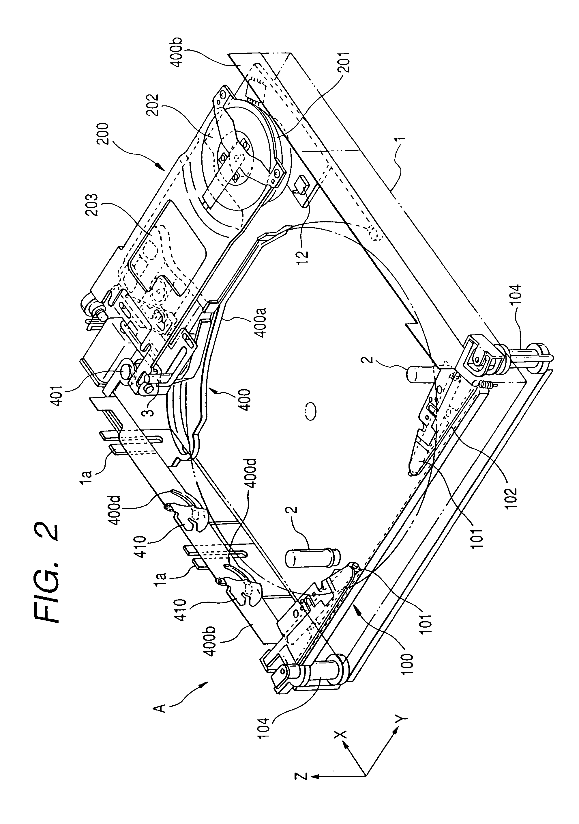
[0040]First, the outline of the playback device A will be explained by referring to FIGS. 1 and 2.

[0041]FIG. 1 is an overall perspective view of the playback device A applying this invention and FIG. 2 is a partial perspective view with one part omitted from the playback device A of FIG. 1.

[0042]In a main chassis 1 of the playback device A are installed at their corresponding positions a recording medium loading mechanism (hereinafter referred to as a loading mechanism) 100 for loading and unloading the recording medium B (shown in FIG. 2); an accommodation unit 300 for accommodatin...


PUM

PropertyMeasurementUnit
widthaaaaaaaaaa
sizeaaaaaaaaaa
diameteraaaaaaaaaa

Abstract

A recording medium playback device includes a recording medium accommodation unit, a carriage chassis having a pickup, a turntable and a pickup moving device, and a moving device. The moving device moves the carriage chassis from a standby position to a position between recording mediums accommodated in the recording medium accommodation unit to play back a recording medium. The recording medium loading device loads the recording medium inserted from outside into the recording medium accommodation unit. Also, when the carriage chassis is in the standby position, the pickup is situated on a vertical tangential plane tangent to an outer circumferential edge of the recording medium on the carriage chassis side at a point where the outer circumferential edge is intersected by a loading center line of the recording medium when the recording medium is completely loaded in the recording medium accommodation unit by the recording medium loading device.

Description

BACKGROUND OF THE INVENTION[0001]The present invention relates to a recording medium playback device capable of playing back a recording medium already recorded with information or of recording information on an information-recordable medium, and more particularly to a recording medium playback device which is reduced in size to facilitate its installation in vehicles.[0002]Among the conventional recording medium playback devices capable of playing back a recording medium already recorded with information or of recording information on an information-recordable medium (hereinafter referred to as a playback device) is a playback device which has a plurality of recording media automatically arrayed and accommodated inside the playback device and which selects an arbitrary recording medium for playback, as described in JP-A-10-337145 previously filed by the applicant of this invention.[0003]This playback device a is shown in FIG. 25. When a user inserts a recording medium c from an ins...

Claims


Application Information

Patent Timeline
Patent Type & Authority Patents(United States)
IPC IPC(8): G11B17/28G11B17/22G11B21/02G11B17/26
CPCG11B17/021G11B17/223G11B17/22
Inventor SUZUKI, TORUYOSHIDA, SUSUMUNAKAMURA, KENJI
Owner PIONEER CORP
Learn More