System for estimating a quantity of parasitic leakage from a fuel injection system

a fuel injection system and parasitic leakage technology, applied in the direction of fluid tightness measurement, electrical control, instruments, etc., can solve the problems of inability to accurately estimate the quantity of parasitic leakage from the fuel injection system, the difficulty of implementing conventional control approaches such as open-loop look-up tables, and the cost of traditional manufacturing approaches to improve performan

Inactive Publication Date: 2006-01-31
CUMMINS INC
View PDF3 Cites 28 Cited by
  • Summary
  • Abstract
  • Description
  • Claims
  • Application Information

AI Technical Summary

Problems solved by technology

However, conventional manufacturing approaches for improving performance, such as tightening tolerances and the like, are typically cost prohibitive, and conventional control approaches such as open-loop look-up tables have become increasingly complex and difficult to implement as the number of degrees of freedom to control have increased, particularly with multiple-input, multiple-output (MIMO) control systems.
In fact, both of these approaches improve accuracy only during engine operation immediately after calibration in a controlled environment, and neither compensate for deterioration or environmental noise changes, which affect subsequent performance.
For example, a primary drawback is that prior art systems of the type illustrated in FIG. 3 are operable to compensate for variations in only a single operating parameter.
Control over variations in additional parameters would require prohibitively large and difficult to manage multi-dimensional look-up tables, wherein such tables would be limited to only operating parameters capable of compensation via look-up table techniques.
For operating parameters that deteriorate or change with time, for example, compensation via look-up tables simply does not work without some type of scheme for updating such tables to reflect changes in those operating parameters.
As another drawback of prior art systems of the type illustrated in FIG. 3, such systems are not closed-loop with respect to injector-to-injector fueling variations.
As is apparent from plot 35, the between-cylinder fuel injection quantity variations are quite pronounced and generally unacceptable in terms of accurate fueling control.
While known cylinder balancing techniques could reduce such cylinder-to-cylinder fueling variations, the fuel control system of FIG. 3 would be ineffective in reducing such variations.
Moreover, the fuel control system of FIG. 3 would further be ineffective in reducing engine-to-engine fueling variations.
Unfortunately, the prior art fuel control system of FIG. 3 cannot compensate for such engine-to engine fueling variations.
In general, if such control parameter variations are not attributable to the operating parameter for which the system is designed to compensate for, but are instead attributable to other error sources for which the control system of FIG. 3 is not designed to compensate for, the system performance may actually be worse than would otherwise be the case with conventional fuel control techniques.

Method used


Image

  • System for estimating a quantity of parasitic leakage from a fuel injection system
  • System for estimating a quantity of parasitic leakage from a fuel injection system
  • System for estimating a quantity of parasitic leakage from a fuel injection system

Examples


Embodiment Construction

[0050]For the purposes of promoting an understanding of the principles of the invention, reference will now be made to a number of illustrative embodiments shown in the drawings and specific language will be used to describe the same. It will nevertheless be understood that no limitation of the scope of the invention is thereby intended.

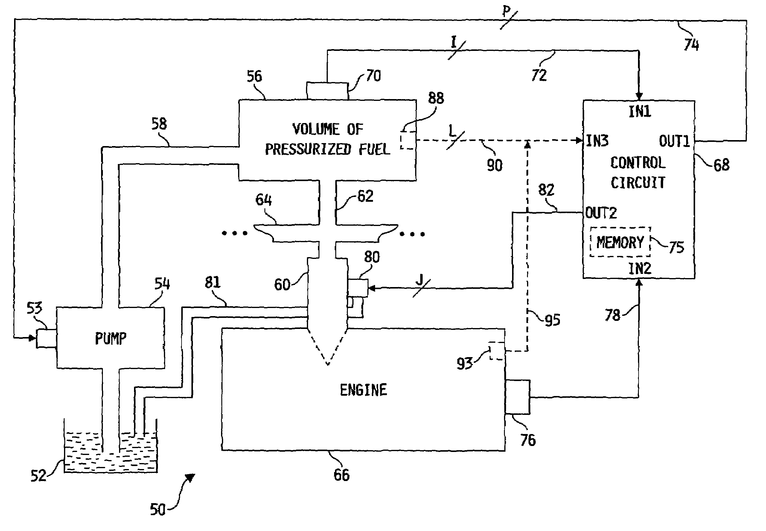
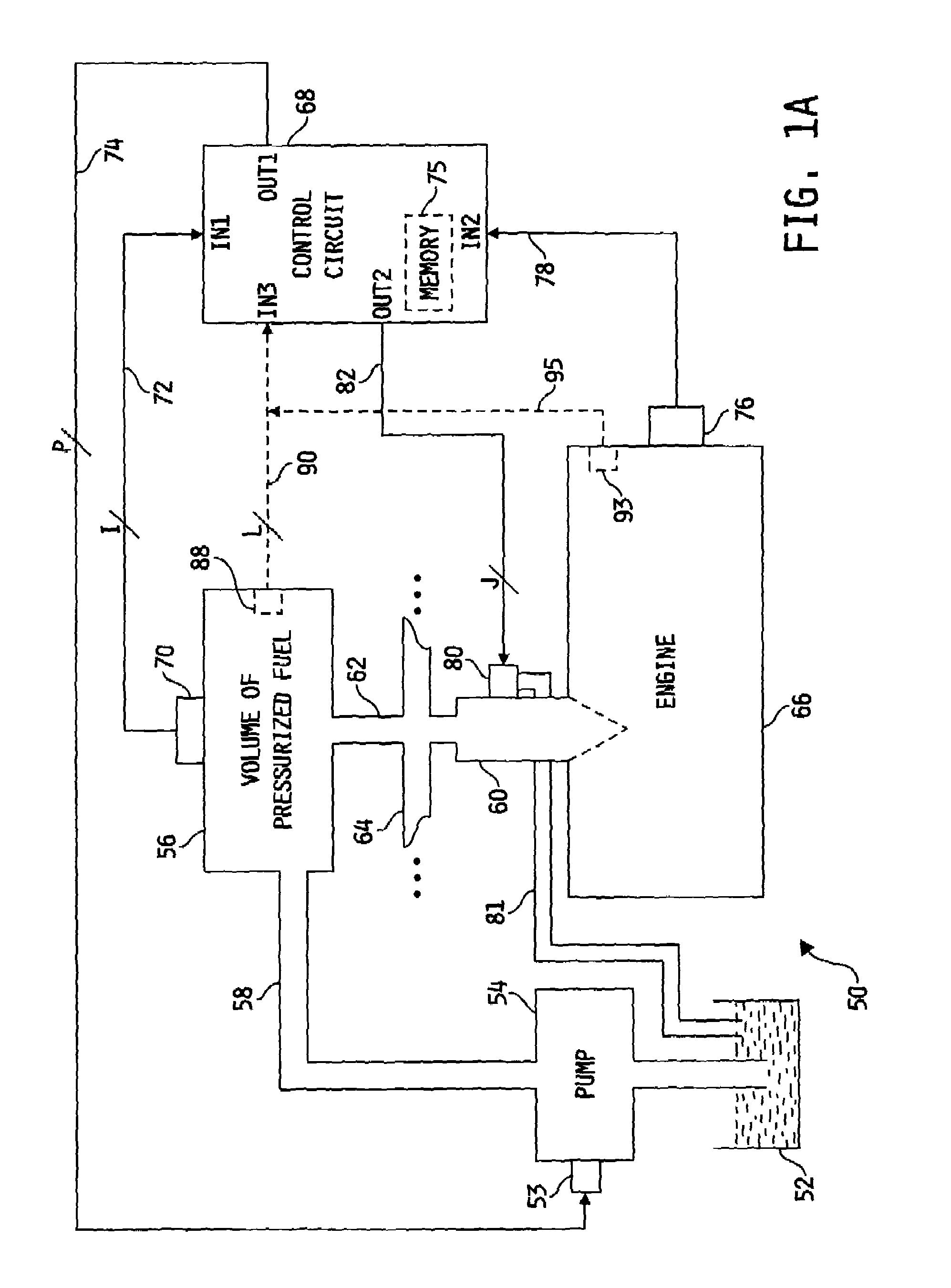
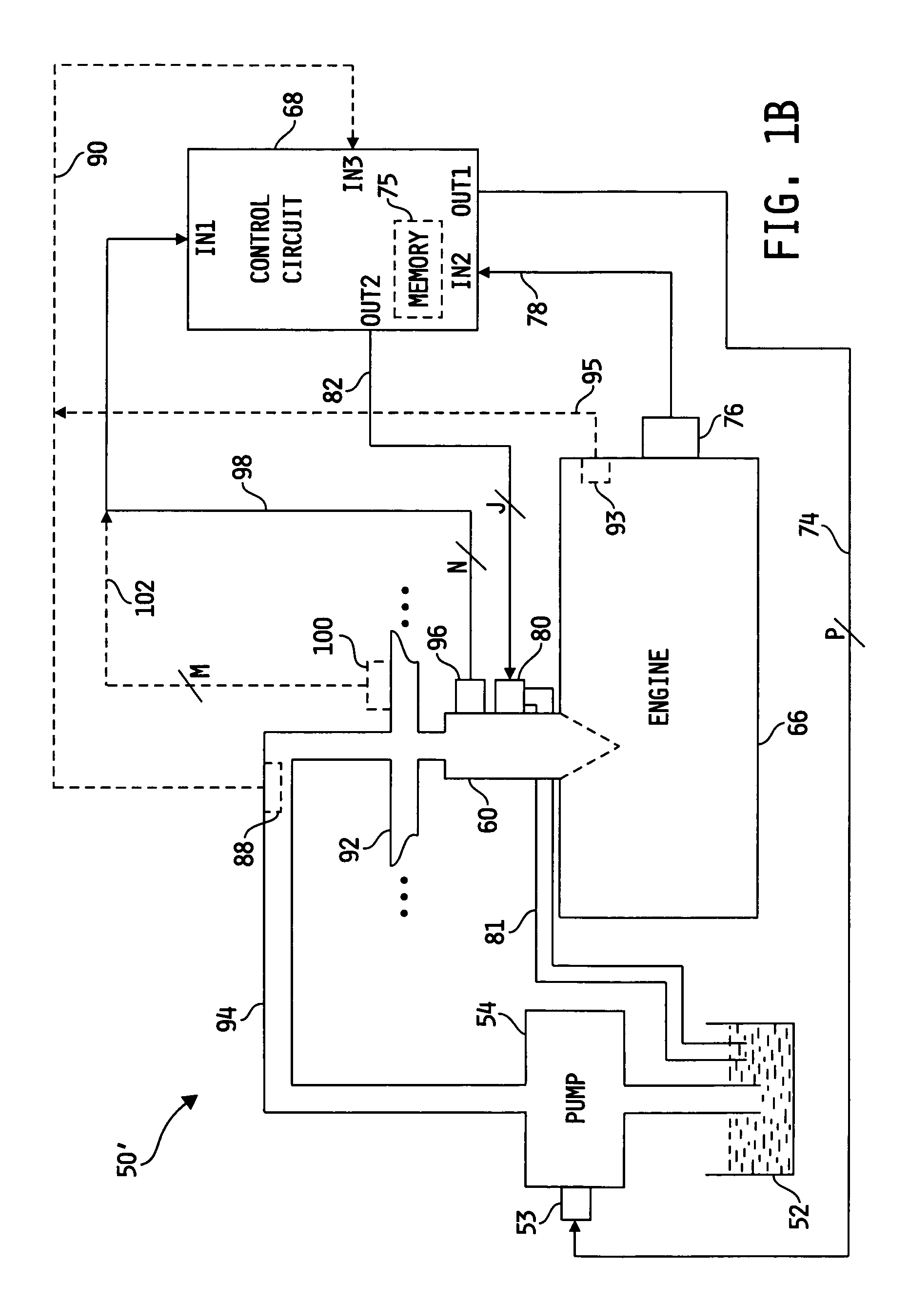
[0051]Referring now to FIG. 1A, one preferred embodiment of an electronic fuel control system 50, in accordance with the present invention, is shown. Fuel control system 50 includes a source of fuel 52; e.g. diesel engine fuel, having an inlet port of a fuel pump 54 in fluid communication therewith. In one embodiment, fuel pump 54 is a high pressure pump configured to supply high pressure fuel from fuel supply 52, which may typically be a low pressure fuel supply pump operable to supply low pressure fuel from a fuel source to,fuel pump 54, to at least one outlet port thereof in a cyclic fashion. It is to be understood, however, that the present inven...


PUM


Abstract

A system for estimating a quantity of parasitic leakage of a fluid from a fluid collection unit includes a pressure sensor and a control circuit. The pressure sensor is coupled to the fluid collection unit and configured to produce a pressure value indicative of the pressure of the fluid collection unit. The control circuit is operable to determine a change in pressure value of the fluid collection unit and estimate the quantity of parasitic leakage based on the change in pressure value. The control circuit may also be operable to determine a bulk modulus value of the fluid and estimate the quantity of parasitic leakage based on the change in pressure value and the bulk modulus value.

Description

CROSS-REFERENCE TO RELATED U.S. PATENT APPLICATION[0001]This is a continuation-in-part of U.S. patent application Ser. No. 10 / 417,829, filed Apr. 17, 2003 now U.S. Pat. No. 6,823,834, and entitled SYSTEM FOR ESTIMATING AUXILIARY-INJECTED FUELING QUANTITIES which is a continuation-in-part of U.S. patent application Ser. No. 09 / 565,010, filed on May 4, 2000, now U.S. Pat. No. 6,557,530, and entitled FUEL CONTROL SYSTEM INCLUDING ADAPTIVE INJECTED FUEL QUANTITY ESTIMATION.FIELD OF THE DISCLOSURE[0002]The present invention relates generally to fuel injection systems for internal combustion engines, and more specifically to techniques for estimating pilot and / or post-injected fuel-quantities and minimizing variations between such fuel quantities.BACKGROUND OF THE DISCLOSURE[0003]In recent years, advances in fuel systems for internal combustion engines, and particularly for diesel engines, have increased dramatically. However, in order to achieve optimal engine performance at all operatin...

Claims


Application Information

Patent Timeline
Patent Type & Authority Patents(United States)
IPC IPC(8): G01M15/00F02D41/24F02D41/38F02D41/40
CPCF02D41/2496F02D41/3809F02D41/40Y02T10/44F02D2041/224F02D2200/0612Y02T10/40
Inventor TUKEN, TANERBENSON, DONALD J.CARROLL, III, JOHN T.TARR, YUL J.CAREY, DAVID M.
Owner CUMMINS INC
Why Eureka
Try Eureka