Supercharge Your Innovation With Domain-Expert AI Agents!

Card ejecting mechanism

a card and ejection mechanism technology, applied in the field of forcible ejection of cards, can solve the problems of difficult to take out cards, card cannot be processed, jams may occur, etc., and achieve the effect of reducing the size and without wasteful spa

Inactive Publication Date: 2006-01-31
SANKYO SEIKI MFG CO LTD
View PDF10 Cites 4 Cited by
  • Summary
  • Abstract
  • Description
  • Claims
  • Application Information

AI Technical Summary

Benefits of technology

[0011]Therefore, since the card forcible ejection mechanism can be set only in the vicinity of the card insertion opening so as to discharge the card retained in the card reader to the card insertion opening, the card forcible ejection mechanism does not have to be provided over the entire card carriage path, thereby reducing the card forcible ejection mechanism in size. Accordingly, even if the card reader with a small empty space is used, the card forcible ejection mechanism can be provided thereto.
[0013]Additionally, in the present invention, the card carrying means includes carriage rollers, and the entire card forcible ejection mechanism may be accommodated between the adjacent carriage rollers in the carriage direction. In this case, the card forcible ejection mechanism realized as a unit can be accommodated within the card reader without producing a wasteful space. Therefore, the card reader can be reduced in size.
[0014]Further, in the present invention, the shutter which opens and closes the card insertion opening is provided, and the claw protruding position is arranged on the shutter side away from the claw retracting position so that the card may be forcibly discharged only when the shutter cannot be closed because it is in contact with the retained card.
[0015]In this case, since discharging the card only when the retained card obstructs the closing operation of the shutter can suffice, the card forcible ejection mechanism can be provided only in the vicinity of the shutter. As a result, the card forcible ejection mechanism does not have to be provided over the entire card carriage path, and the card forcible-ejection mechanism can be reduced in size.
[0016]Further, since the retained card is immediately discharged and returned to a user when the shutter is not closed, it is possible to prevent a stranger from stealing the card when the card is retained with the shutter being not closed and a user walks away from the card reader.

Problems solved by technology

However, when a deformed card or a stained card is inserted into the card reader, a so called jam that the card is retained in a card carriage path may occur, and the card cannot be processed in some cases.
Further, even in case of a normal card, the jam may occur if a person who tries to steal any other person's card manipulates a part of the card reader in the vicinity of a card insertion opening thereof.
In this case, even if the card generates the jam and the card owner leaves there, it is difficult to take out the card when a shutter of the card insertion opening is completely closed.
Therefore, a possibility of a theft is small.
However, when the card stays in a movement range of the shutter and the shutter cannot closes because it is in contact with the card, the card may be possibly taken out after the card owner leaves there.
However, in the above-described card forcible ejection mechanism, since the chain 90 is provided over the entire area of the card carriage path 80 in order to feed the card retained in the card carriage path 80 to the card insertion opening 88 or the card disposition box, an empty space may be insufficient and the card forcible ejection mechanism may not be provided depending on a structure of the card reader.
Moreover, since the card forcible ejection mechanism has a large size that it extends over the entire area of the card carriage path 80, it is very difficult to provide this mechanism to the card reader on a post-assembling step as an option.

Method used


Image

  • Card ejecting mechanism
  • Card ejecting mechanism
  • Card ejecting mechanism

Examples


Embodiment Construction

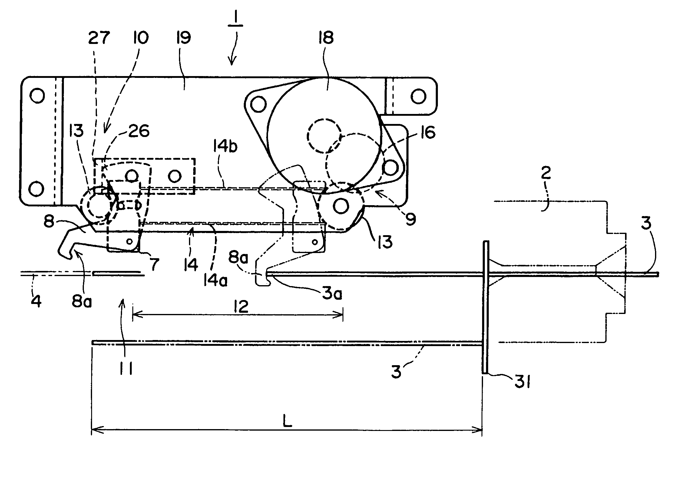
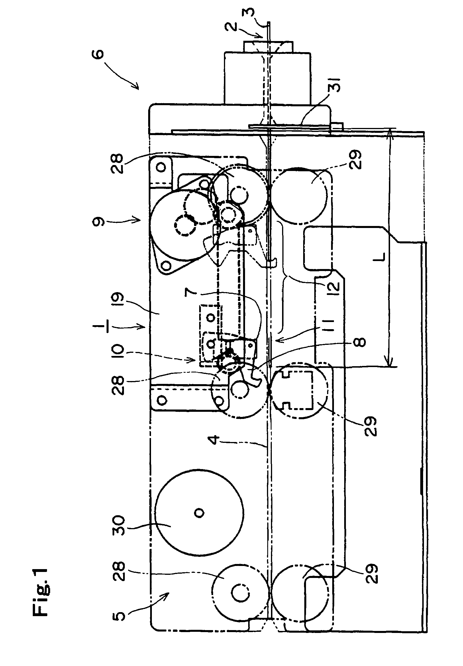
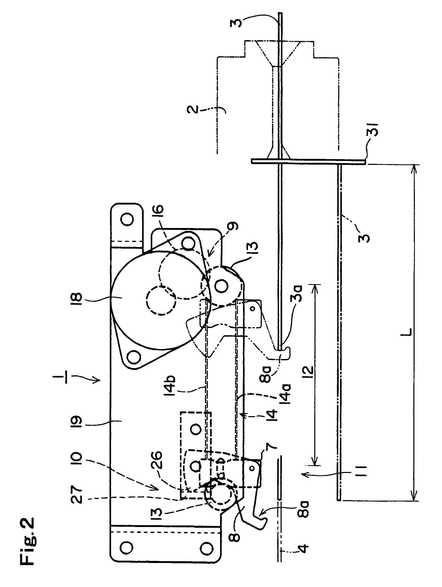
[0029]A structure of the present invention will now be described in detail hereinafter based on an example of the illustrated mode. FIGS. 1 to 6 show an embodiment of a card forcible ejection mechanism 1 according to the present invention. This card forcible ejection mechanism 1 is provided to a card reader 6 including a card carrying means 5 for carrying a card 3 inserted from a card inserting opening 2 in a card carriage path 4, and forcibly ejects the card 3 retained in the card carriage path 4. This card forcible ejection mechanism 1 includes a carriage 7 which can move in a carriage direction of the card 3 and is provided separately from the card carrying means 5, at least one claw 8 which can protrude / retract to / from the card carriage path 4, carriage moving means 9 for moving the carriage 7, and a claw protruding / retracting mechanism 10 which protrudes / retracts the claw to / from the card carriage path 4. Further, the entire card forcible ejection mechanism 1 is realized as a u...


PUM

PropertyMeasurementUnit
lengthaaaaaaaaaa
areaaaaaaaaaaa
sizeaaaaaaaaaa

Abstract

A card forcible ejection mechanism used to forcibly discharge a card retained in a card reader can be set in a small space and can be attached during a post-assembling step. The mechanism has a carriage which can move along a carriage direction of a card and is provided separately from a card carrying device and at least one claw which is provided on the carriage and can protrude / retract to / from a card carriage path: A carriage moving device for moving the carriage to a claw retracing position and a claw protruding position, and a claw protruding / retracting mechanism which retracts the claw from the card carriage path when the carriage is placed at the claw retracting position and protrudes the claw to the card carriage path when the carriage is placed at the claw protruding position, are also provided.

Description

TECHNICAL FIELD[0001]The present invention relates to a card forcible ejection mechanism provided to a card reader using a card having a magnetic stripe, an IC card, or various kinds of cards on which information can be recorded. More particularly, the present invention relates,to a card forcible ejection mechanism used to forcibly eject a card retained inside a card reader.BACKGROUND ART[0002]If a card to be inserted into a card reader is a normal card without a deformation or a stain, carriage of the card in the card reader can be performed without causing any problem. However, when a deformed card or a stained card is inserted into the card reader, a so called jam that the card is retained in a card carriage path may occur, and the card cannot be processed in some cases.[0003]Further, even in case of a normal card, the jam may occur if a person who tries to steal any other person's card manipulates a part of the card reader in the vicinity of a card insertion opening thereof. In ...

Claims


Application Information

Patent Timeline
Patent Type & Authority Patents(United States)
IPC IPC(8): G06K13/04B42D25/20B42D25/30B42D25/305B65H9/10B65H29/00G06K13/08
CPCB65H9/101B65H29/00G06K13/0806G06K13/08B65H2301/442B65H2701/1914B65H2404/733
Inventor HIRASAWA, KENJINAGATA, SHIGEYUKI
Owner SANKYO SEIKI MFG CO LTD
Features
  • R&D
  • Intellectual Property
  • Life Sciences
  • Materials
  • Tech Scout
  • Unparalleled Data Quality
  • Higher Quality Content
  • 60% Fewer Hallucinations
Learn More