Panel mount cable connector assembly

a panel mount cable and connector technology, applied in the direction of coupling device connection, coupling device details, coupling protective earth/shielding arrangement, etc., can solve the problems of inconvenient panel mount connector assembly, inconvenient panel mount connector structure, and inability to meet the needs of panel mount connectors, etc., to achieve the effect of improving the high speed signal transmitting

Inactive Publication Date: 2006-01-31
HON HAI PRECISION IND CO LTD
View PDF5 Cites 33 Cited by
  • Summary
  • Abstract
  • Description
  • Claims
  • Application Information

AI Technical Summary

Benefits of technology

[0006]Accordingly, an object of the present invention is to provide a cable connector assembly with better high speed signal transmitting effect.
[0007]In order to achieve the object set forth, a cable connector assembly in accordance with the present invention comprises an electrical connector comprising an insulative housing, a plurality of conductive contacts received in the insulative housing and a conductive shield attaching to the insulative housing, a cable comprising a plurality of lines, a printed circuit board electrically connecting the conductive contacts of the electrical connector with the lines of the cable, and a shielding member electrically connecting with the electrical connector and secured with the printed circuit board and the cable. The shielding member forms a plurality of deflecting members for securing to a panel and a plurality of anti-stress members for preventing the deflecting members from excessive deformation.

Problems solved by technology

However, when the cable connector assembly needs to transmit high speed signals, grounding becomes an important issue.
However, the structure of the capacitive coupling adapter is relatively complex and cost consuming.
In addition, the structure of the panel mount connector is not suitable for a panel mount cable connector assembly.

Method used


Image

  • Panel mount cable connector assembly
  • Panel mount cable connector assembly
  • Panel mount cable connector assembly

Examples


Embodiment Construction

[0017]Reference will now be made in detail to the preferred embodiment of the present invention.

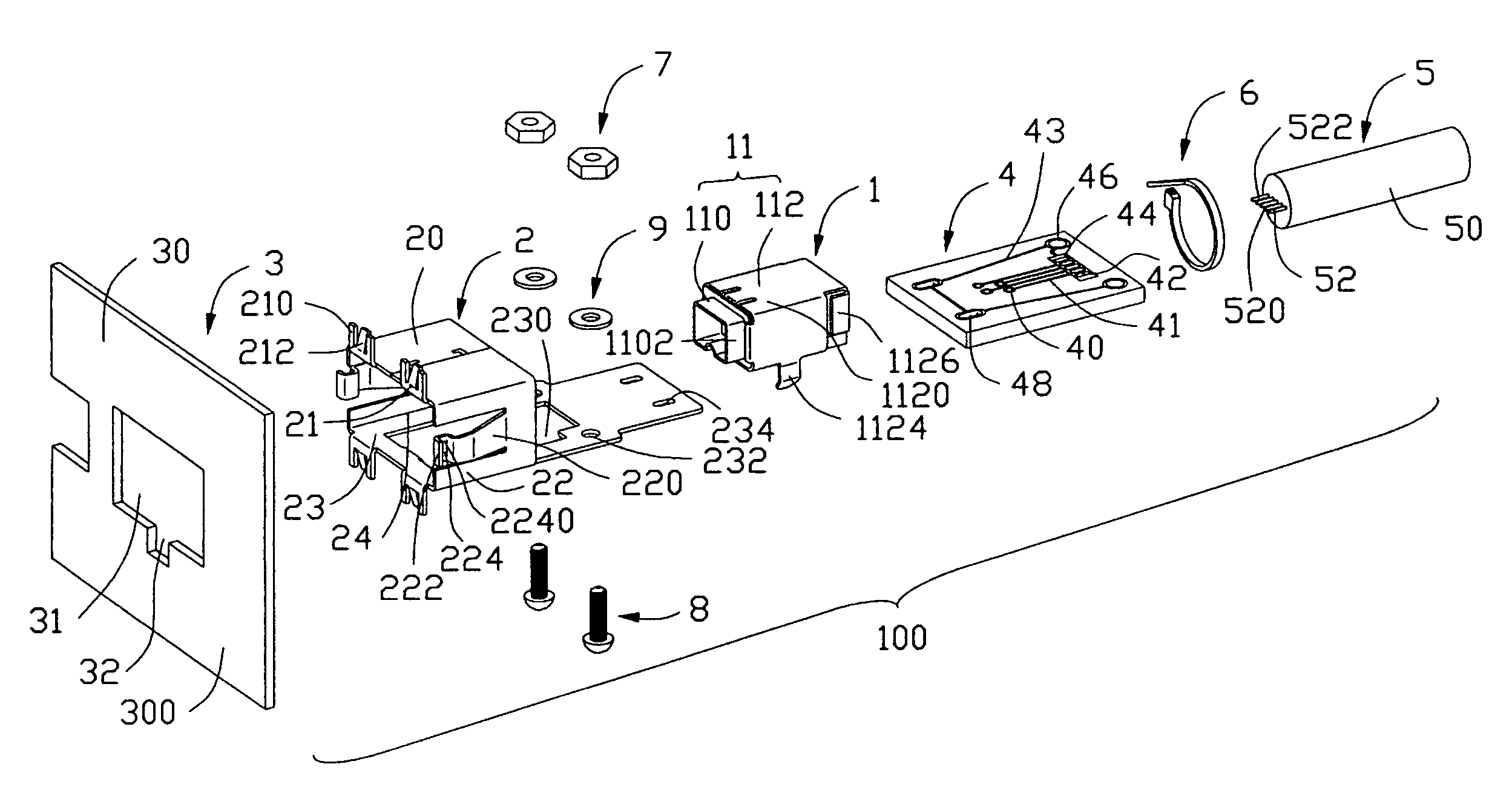
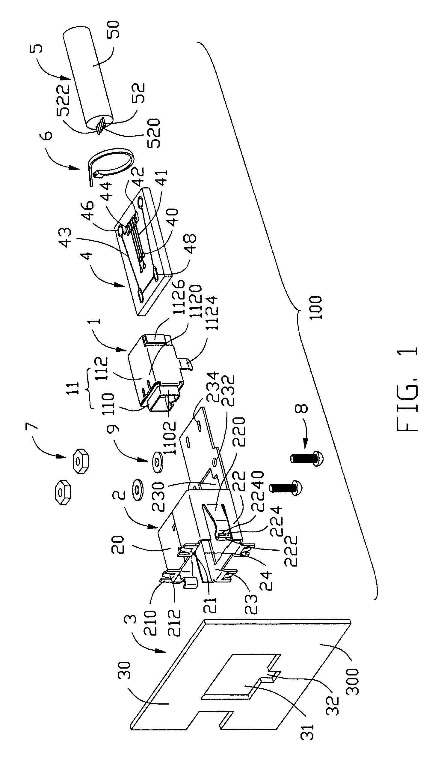
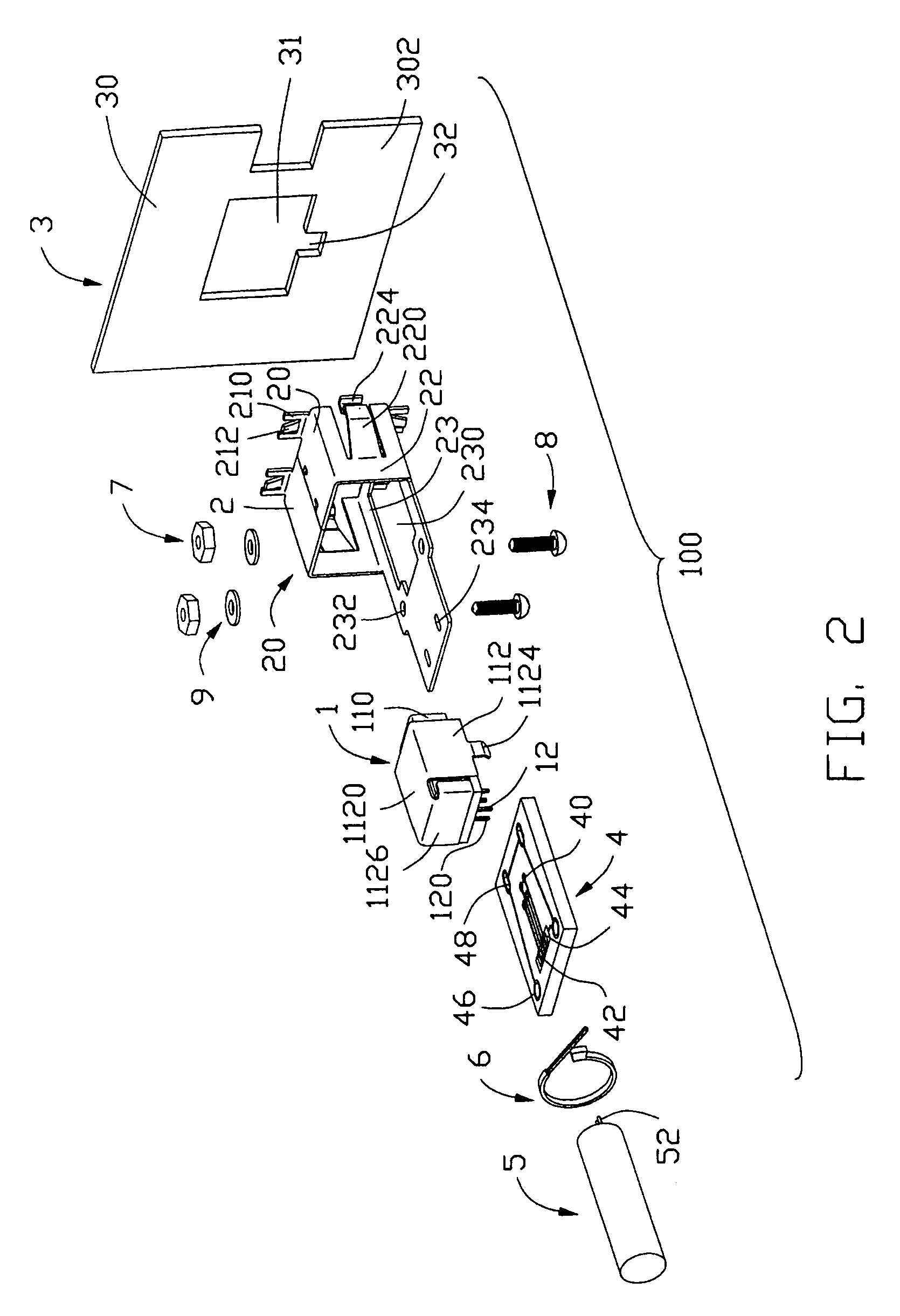
[0018]Referring to FIGS. 1–2, a cable connector assembly 100 in accordance with the present invention comprises an electrical connector 1, a shielding member 2 surrounding the electrical connector 1, a panel 3, a printed circuit board 4, a cable 5, a band strip 6, a pair of screw nuts 7, a pair of screw bolts 8 and a pair of washers 9.

[0019]Referring to FIGS. 1–2 in conjunction with FIGS. 7–8, the electrical connector 1 comprises an insulative housing 10, a plurality of conductive contacts 12 retained in the insulative housing 10, and a conductive shield 11 enclosing the insulative housing 10.

[0020]Particularly referring to FIG. 7 in conjunction with FIGS. 1–2, the insulative housing 10 comprises a rectangular body portion 106 and a tongue portion 104 extending forwardly from the body portion 106. A plurality of passageways 102 extend rearwardly from a front surface of the tongue portion ...


PUM


Abstract

A cable connector assembly (100) includes an electrical connector (1) including an insulative housing (10), a number of conductive contacts (12) received in the insulative housing and a conductive shield (11) enclosing the insulative housing, a cable (5) including a number of lines (520, 522), a printed circuit board (4) electrically connecting the conductive contacts of the electrical connector with the lines of the cable, and a shielding member (2) electrically connecting with the electrical connector and secured with the printed circuit board and the cable. The shielding member forms a number of deflecting members (212) for securing to a panel (3) and a number of anti-stress members for preventing the deflecting members from excessive deformation.

Description

BACKGROUND OF THE INVENTION[0001]1. Field of the Invention[0002]The present invention generally relates to a cable connector assembly, and more particularly to a panel mount cable connector assembly.[0003]2. Description of Related Art[0004]A panel mount cable connector assembly located in a chassis of a computer usually comprises an insulative housing, a plurality of conductive contacts received in the housing, a cable electrically connecting with the conductive contacts. A front portion of the insulative housing is configured to engage with a panel of a chassis and is exposed beyond the panel for engaging with a complementary connector. U.S. Pat. No. 6,030,242 discloses such a panel mount cable connector assembly. However, when the cable connector assembly needs to transmit high speed signals, grounding becomes an important issue. U.S. Pat. No. 5,975,958 discloses a panel mount connector engaging with a panel through a capacitive coupling adapter and electrically connecting with a ...

Claims


Application Information

Patent Timeline
Patent Type & Authority Patents(United States)
IPC IPC(8): H01R13/648H01R13/658H01R13/66H01R13/74
CPCH01R13/745H01R13/65802H01R2201/06H01R13/6658H01R13/6582
Inventor SPINK, JR., WILLIAM E.
Owner HON HAI PRECISION IND CO LTD
Why Eureka
Try Eureka