Manual engine starter

a starter and engine technology, applied in the direction of engine starters, muscle operated starters, machines/engines, etc., can solve the problems of wasting engine energy and the inability to use conventional engine starters, so as to prevent engine wasting energy and effectively the effect of the engin

Inactive Publication Date: 2006-02-07
LIU NAI WEN
View PDF1 Cites 5 Cited by
  • Summary
  • Abstract
  • Description
  • Claims
  • Application Information

AI Technical Summary

Benefits of technology

[0008]The main objective of the present invention is to provide an improved manual engine starter that can effectively the engine and prevent the engine from wasting energy.

Problems solved by technology

It will cause a disadvantage of wasting energy to the engine (1).
In addition, the friction between the stub (4B) and the distal face (5A) will offset some power from the engine, and the conventional engine starter may not be used when the stub (4B) is worn out.

Method used


Image

  • Manual engine starter
  • Manual engine starter
  • Manual engine starter

Examples


Embodiment Construction

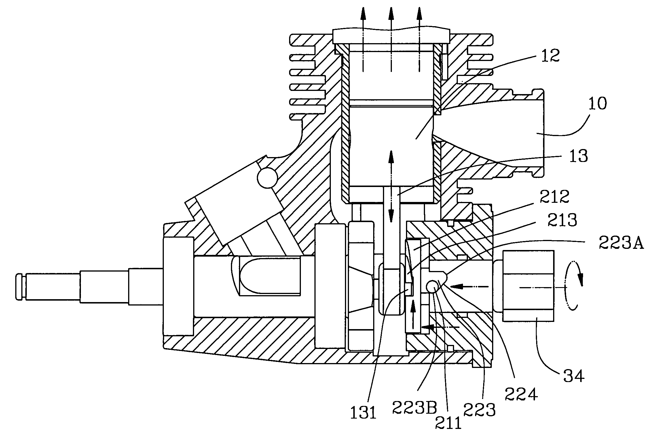
[0019]Referring to the drawings and initially to FIGS. 1–4, a manual engine starter in accordance with the present invention is adapted to be laterally mounted to an engine (10) of a radio control toy. The engine (10) includes a chamber (11) defined therein and a piston (12) reciprocally movably received in the chamber (11). A crank (13) includes a first end pivotally connected to a bottom of the piston (12) and a second end having a protrusion (131) laterally extending therefrom toward the manual engine starter on the present invention.

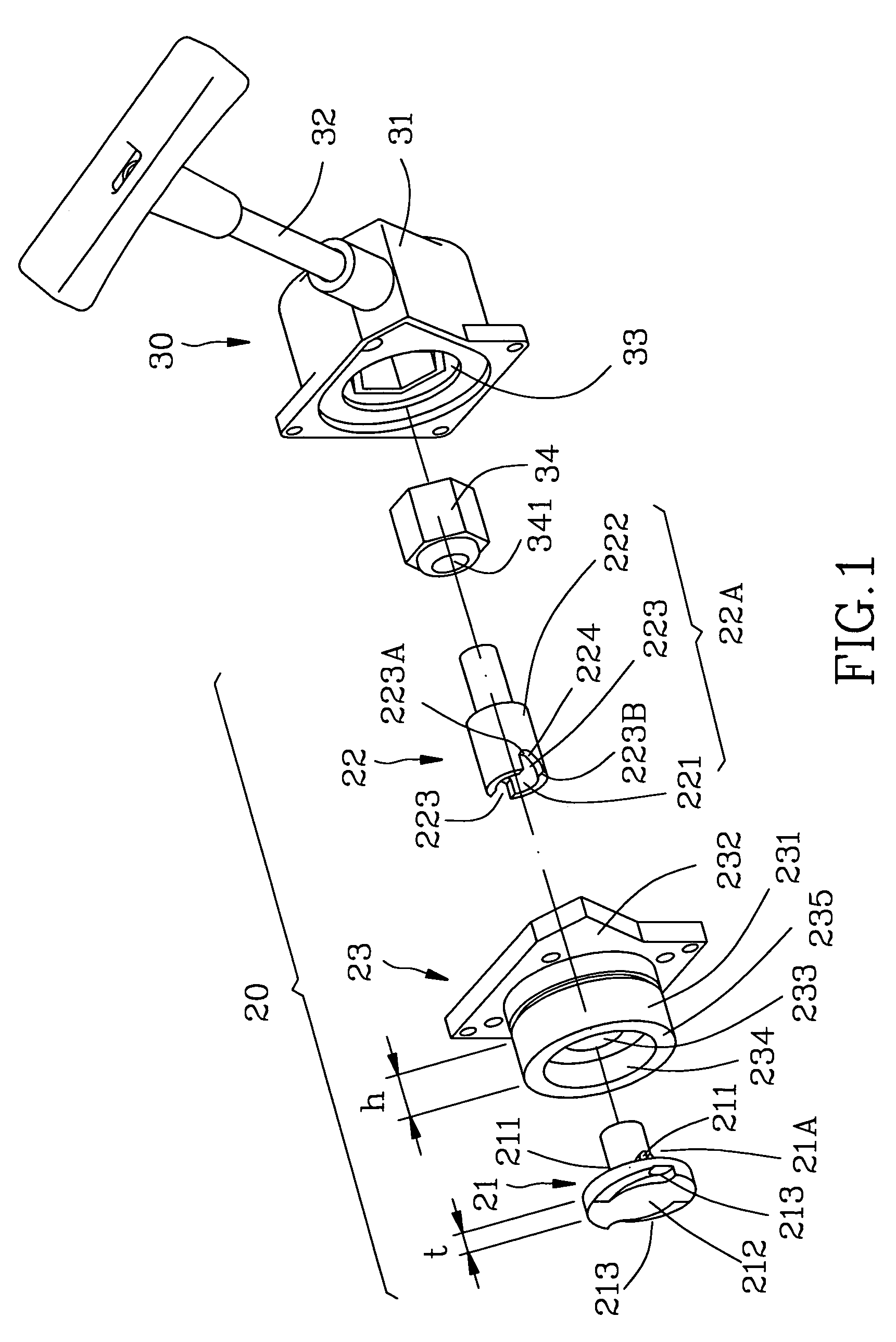
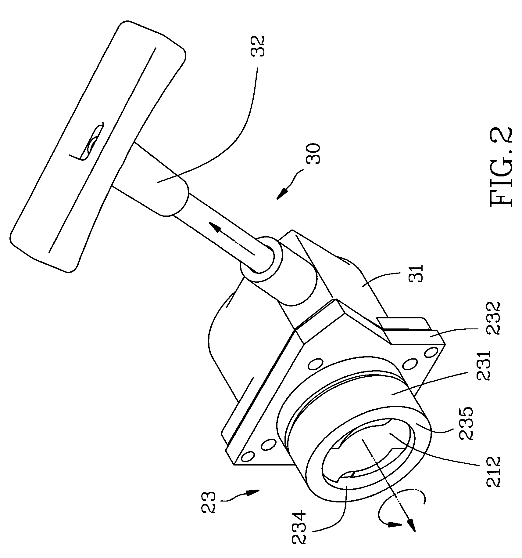
[0020]The manual engine starter in accordance with the present invention comprises a starting device (20) laterally mounted to the engine and selectively connected to the protrusion (131), and a puller (30) laterally mounted to the starting device (20) for driving the starting device (20).

[0021]The puller (3) includes a housing (31) secured on the starting device (20) and a polygonal seat (33) is reciprocally rotatably received in the housing (31) fo...


PUM


Abstract

A manual engine starter includes a starting device having a driven shaft selectively connected to a crank of the engine and a drive shaft connected to the driven shaft for driving the driven shaft and starting the engine. The drive shaft has a tubular drive portion formed with a guide side and the driven shaft having a driven portion that is rotatably received in the tubular drive portion and engaged to the guide side and moved along the guide so as to make the driven shaft moved along an axis thereof when the drive shaft is rotated to drive the driven shaft. A puller laterally is mounted the starting device for driving the drive shaft to drive the driven shaft.

Description

BACKGROUND OF THE INVENTION[0001]1. Field of the Invention[0002]The present invention relates to an engine starter, and more particularly to a manual engine starter for a radio control vehicle.[0003]2. Description of Related Art[0004]A conventional manual engine starter in accordance with the prior art shown in FIG. 7 comprises a T-shape shaft (5) having a first end connected to a free end of a crank (4) that is longitudinally secured to a bottom of the piston (3). The piston (3) is reciprocally movably received in a chamber (2) in the engine (1). The T-shaped shaft (5) has a second end detachably connected to a puller (6). The puller (6) can instantly rotate the T-shape shaft (5) to sequentially drive the crank (4) and the piston (3) and make the piston (3) be reciprocally moved in the chamber (2) for starting the engine (1). However, the T-shaped shaft (5) does not disengage from the crank (4) after the engine (1) being started and is rotated due to the operating engine (1). It wi...

Claims


Application Information

Patent Timeline
Patent Type & Authority Patents(United States)
IPC IPC(8): F02N3/02F02N1/00
CPCF02N3/02Y10T74/134
Inventor LIU, NAI WEN
Owner LIU NAI WEN
Why Eureka
Try Eureka