Linear displacement measurement method and apparatus

a measurement method and linear displacement technology, applied in survey, borehole/well accessories, construction, etc., can solve the problems of cable degradation, increased production costs, and flow from a particular location along the production tubing

Inactive Publication Date: 2006-02-07
WEATHERFORD TECH HLDG LLC
View PDF22 Cites 80 Cited by
  • Summary
  • Abstract
  • Description
  • Claims
  • Application Information

AI Technical Summary

Benefits of technology

[0009]The present invention generally relates to methods and apparatus for detecting an operation of a downhole tool. In an embodiment, a flow control device has an inner tubular member moveable relative to an outer tubular member and a thermally responsive chamber capable of a change in temperature during a movement between the inner tubular member and the outer tubular member. Detecting the change in temperature in the thermally responsive chamber with an optical sensing system provides real time knowledge of the position of the flow control device. In another embodiment, a flow control device has an inner tubular member moveable relative to an outer tubular member that produces an acoustic signal during a movement between the inner tubular member and the outer tubular member. Detecting the acoustic signal with an optical sensor provides real time knowledge of the position of the flow control device.

Problems solved by technology

For example, the flow from a particular location along the production tubing may need to be restricted due to production of water that can be detrimental to wellbore operations since it decreases the production of oil and must be separated and disposed of at the surface of the well which increases production costs.
However, problems associated with electrical cables include degradation of the cable and significant cable resistance due to long electrical path lengths downhole that require both large power requirements and the use of large cables within a limited space available in production strings.
Additionally, electrical sensors comprising inherently complex electronics prone to many different modes of failure must be extremely reliable since early failure may require a very time consuming and expensive well intervention for replacement.
There are numerous other problems associated with the transmission of electrical signals within wellbores including difficulties encountered in providing an insulated electrical conductor due to the harsh environment and interferences from electrical noises in some production operations.
Unlike electrical sensors, optical sensors lack the ability to directly determine whether a mechanical operation downhole has been performed.
For example, optical sensors can not directly determine a position of a sleeve on a flow control device.

Method used


Image

  • Linear displacement measurement method and apparatus
  • Linear displacement measurement method and apparatus
  • Linear displacement measurement method and apparatus

Examples


Embodiment Construction

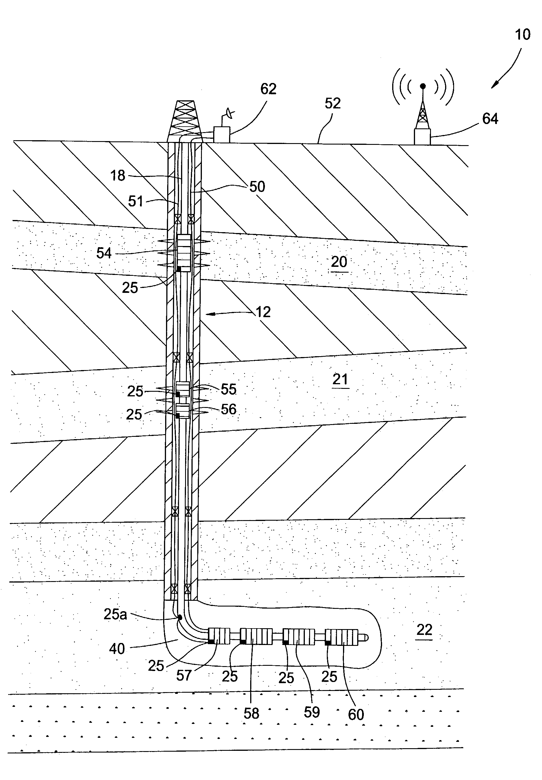
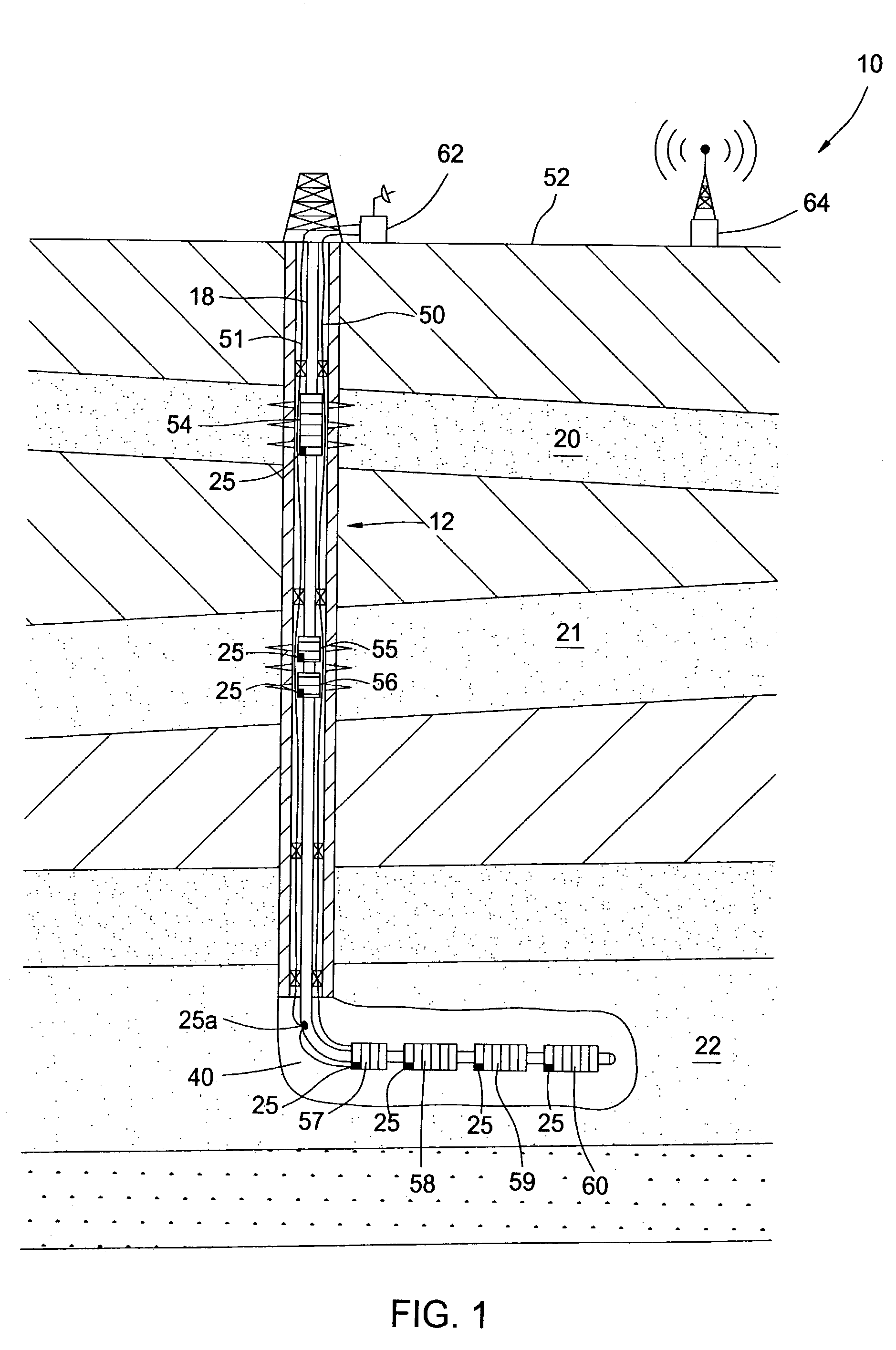
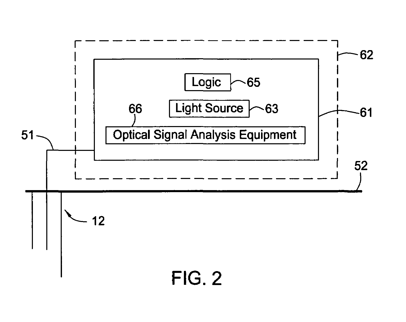
[0020]The present invention generally relates to methods and apparatus for detecting an operation of a downhole tool such as a flow control device by using an optical sensing system. FIG. 1 is a cross-sectional view of a hydrocarbon well 10 having a plurality of flow control devices 54–60 coupled to a string of tubing 18 run in a wellbore 12. Therefore, flow rate from formations 20–22 can be controlled by the flow control devices 54–56 adjacent perforations in a cased portion of the wellbore 12 and the flow control devices 57–60 positioned in an open portion 40 of the wellbore 12. At least one control line 50 and at least one signal line such as an optical fiber 51 containing a light guiding core that guides light along the optical fiber runs from a surface 52 to the flow control devices 54–60.

[0021]The control line 50 and the optical fiber 51 may be disposed independently or together on the outside surface of the tubing 18 by clamps (not shown) that are adapted to cover and protect...


PUM


Abstract

Methods and apparatus for detecting an operation of a downhole tool using an optical sensing system are disclosed. In an embodiment, a flow control device has an inner tubular member moveable relative to an outer tubular member and a thermally responsive chamber capable of a change in temperature during a movement between the inner tubular member and the outer tubular member. Detecting the change in temperature in the thermally responsive chamber with an optical sensing system provides real time knowledge of the position of the flow control device. In another embodiment, a flow control device comprises an inner tubular member moveable relative to an outer tubular member that produces an acoustic signal during a movement between the inner tubular member and the outer tubular member. Detecting the acoustic signal with an optical sensor provides real time knowledge of the position of the flow control device.

Description

BACKGROUND OF THE INVENTION[0001]1. Field of the Invention[0002]Embodiments of the present invention generally relate to apparatus and methods for detecting an operation of a downhole tool. More particularly, embodiments of the present invention generally relate to using optical sensing systems to detect an operation of the downhole tool. More particularly still, embodiments of the present invention generally relate to detecting a position of a flow control device.[0003]2. Description of the Related Art[0004]In the drilling of oil and gas wells, a wellbore is formed using a drill bit that is urged downwardly at a lower end of a drill string. After drilling the wellbore to a predetermined depth, the drill string and bit are removed. Thereafter, the wellbore is typically lined with a string of steel pipe called casing. The casing provides support to the wellbore and facilitates the isolation of certain areas of the wellbore adjacent hydrocarbon bearing formations. It is common to empl...

Claims


Application Information

Patent Timeline
Patent Type & Authority Patents(United States)
IPC IPC(8): E21B44/06E21B29/02E21B47/06E21B47/09E21B47/10E21B47/12
CPCE21B29/02E21B47/065E21B47/123E21B47/101E21B47/09E21B47/07E21B47/107E21B47/135E21B34/10
Inventor ROBISON, CLARK E.
Owner WEATHERFORD TECH HLDG LLC
Why Eureka
Try Eureka