Utility meter power arrangements and methods

a technology of power arrangement and utility meters, applied in the field of utility meters, can solve the problems of increased cost, high power requirements of such radios, labor-intensive and expensive methods of meter reading, etc., and achieve the effect of enhancing the operation of energy storage devices

Active Publication Date: 2006-02-07
LANDIS GYR LLC
View PDF19 Cites 75 Cited by
  • Summary
  • Abstract
  • Description
  • Claims
  • Application Information

AI Technical Summary

Problems solved by technology

Because meters are typically located at the facility of the utility customer, such methods of meter reading are labor intensive and expensive.
One problem with wireless radio communications in utility meters arises from the high power requirements of such radios.
The larger capacity power supply both occupies additional space within the meter and has increased cost.
Because utility meter is only required to perform RF transmissions a very small fraction of the overall operating time of the meter, such additional power generating capacity goes unused for a substantial majority of the time.
As a consequence, the relatively infrequent need for additional power does not necessarily justify the additional size, weight and cost issues that arise from the use of a large capacity power supply.
The reliance on batteries however, has drawbacks.
Indeed, the use of non-rechargeable batteries requiring frequent replacement would defeat the very purpose of implementing radio frequency transmission to reduce the need for service visits to the meter.
However, such batteries are not particularly well-suited to the particular needs of a utility meter.
For example, such batteries require relatively complex charging circuits, which would tend to negate the cost-savings of using the temporary power source.
Moreover, all rechargeable batteries have a limited temperature range.
Some rechargeable batteries lose their ability to hold a charge if exposed to out of range temperatures for an extended period.

Method used


Image

  • Utility meter power arrangements and methods
  • Utility meter power arrangements and methods
  • Utility meter power arrangements and methods

Examples


Embodiment Construction

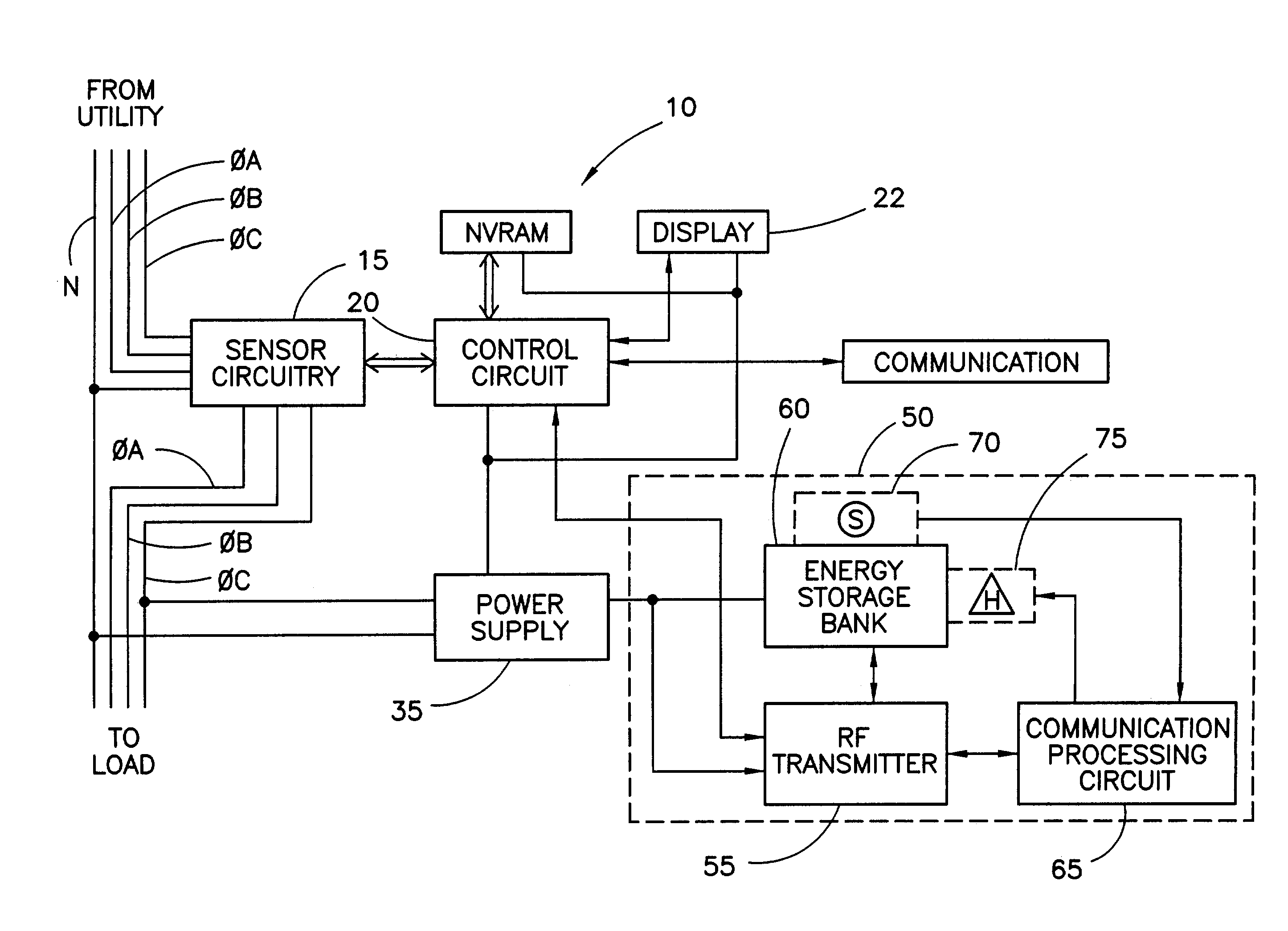
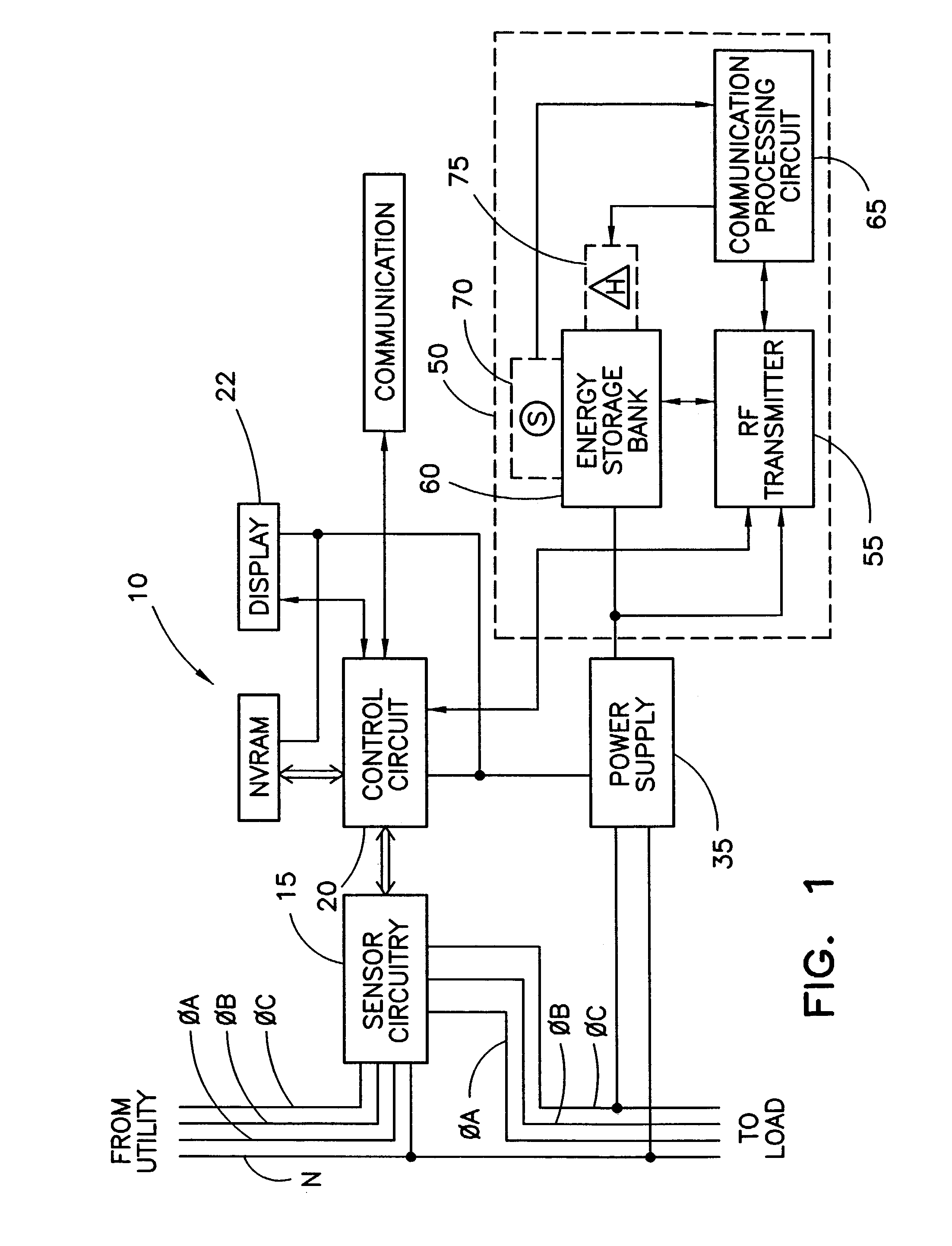
[0019]FIG. 1 shows a block diagram of an electricity meter 10 that incorporates a power arrangement according to the present invention. In general, the meter 10 includes a sensor portion or sensor circuit 15, a primary power supply 35, a measurement portion or measurement circuit 20, a control circuit 30, a communication circuit 45, a radio frequency communication (“RF”) module 50.

[0020]The sensor circuit 15 is operably coupled to a plurality of utility power lines including a phase A power line φA, a phase B power line φB, a phase C power line φC, and a neutral line N. The plurality of utility power lines φA, φB, φC, and N connect to an electrical utility, not shown, and provide power from the utility to a load, not shown. The power or energy consumed by the load is metered by the meter 10. The load may suitably be the electrical system of a residential facility, industrial facility, commercial facility, or the like. It is noted that the exemplary embodiment described herein is ins...


PUM


Abstract

An arrangement for providing power in a utility meter includes a power conversion circuit and a bank of capacitors. The power conversion circuit is operable to provide power to metering circuitry within the utility meter, the power conversion circuit having a maximum output current. The bank of capacitors is operably coupled to a power supply input of the radio frequency transmitter, the bank of capacitors configured to provide current in excess of the maximum output current during transmission by the radio frequency transmitter to supply power to the radio frequency transmitter.

Description

[0001]This application claims the benefit of U.S. Provisional Patent Application Ser. No. 60 / 324,778, filed Sep. 25, 2001, which is incorporated herein by reference.FIELD OF THE INVENTION[0002]The present invention relates generally to utility meters, and more particularly, to arrangements and methods for providing power to circuits within a utility meter.BACKGROUND OF THE INVENTION[0003]Utility meters, such as electricity meters, track the usage of utility commodities, for example, electricity. In the past, utility personnel physically observed meter data on mechanical counters or electronic displays. Because meters are typically located at the facility of the utility customer, such methods of meter reading are labor intensive and expensive.[0004]Various types of remote meter reporting systems have been proposed and / or implemented. In one proposal, a wireless radio is employed. Wireless radio technology provides the advantage of not requiring a separate land-based communication lin...

Claims


Application Information

Patent Timeline
Patent Type & Authority Patents(United States)
IPC IPC(8): G08B23/00G08C19/12G01D4/00H01Q1/22H04Q9/00
CPCG01D4/002H01Q1/22H01Q1/2233H04Q9/00H04B1/04H04Q2209/823Y04S20/32H04Q2209/40H04Q2209/60H04Q2209/88Y02B90/241Y02B90/20Y04S20/30
Inventor RANDALL, BRUCE E.
Owner LANDIS GYR LLC
Why Eureka
Try Eureka