Visual image system

a visual image and system technology, applied in the field of visual image systems, can solve the problems of difficulty in determining the limit value of fatigue measurement suitable for all observers, eye fatigue is more likely to occur, and it is difficult to individually obtain the measurements of each observer

Inactive Publication Date: 2006-02-07
OLYMPUS CORP
View PDF13 Cites 41 Cited by
  • Summary
  • Abstract
  • Description
  • Claims
  • Application Information

AI Technical Summary

Benefits of technology

[0012]The degree of influence produced on the observer is thus estimated from inputted video signal and the displaying method of visual image is controlled on the basis of such influence measure estimating quantity. It is thereby possible to achieve a visual image system in which a suitable control on displayin

Problems solved by technology

It is generally said that the eyes are more likely to become fatigued when observing a stereoscopic image comparing to the case of observing an ordinary two-dimensional image.
In the case of controlling the degree of three-dimensionality of stereoscopic image based on the degree of excitation and degree of fatigue of the user as in the method of the above-mentione

Method used


Image

  • Visual image system
  • Visual image system
  • Visual image system

Examples


Embodiment Construction

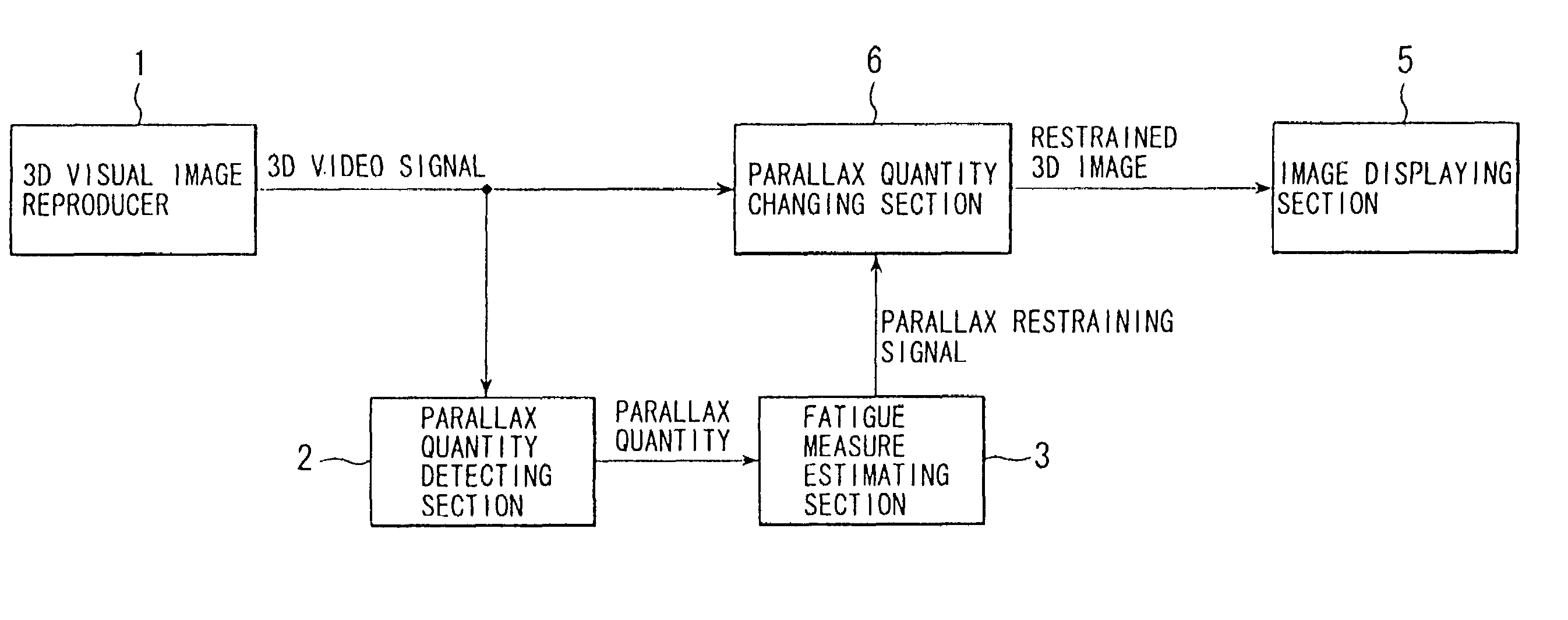
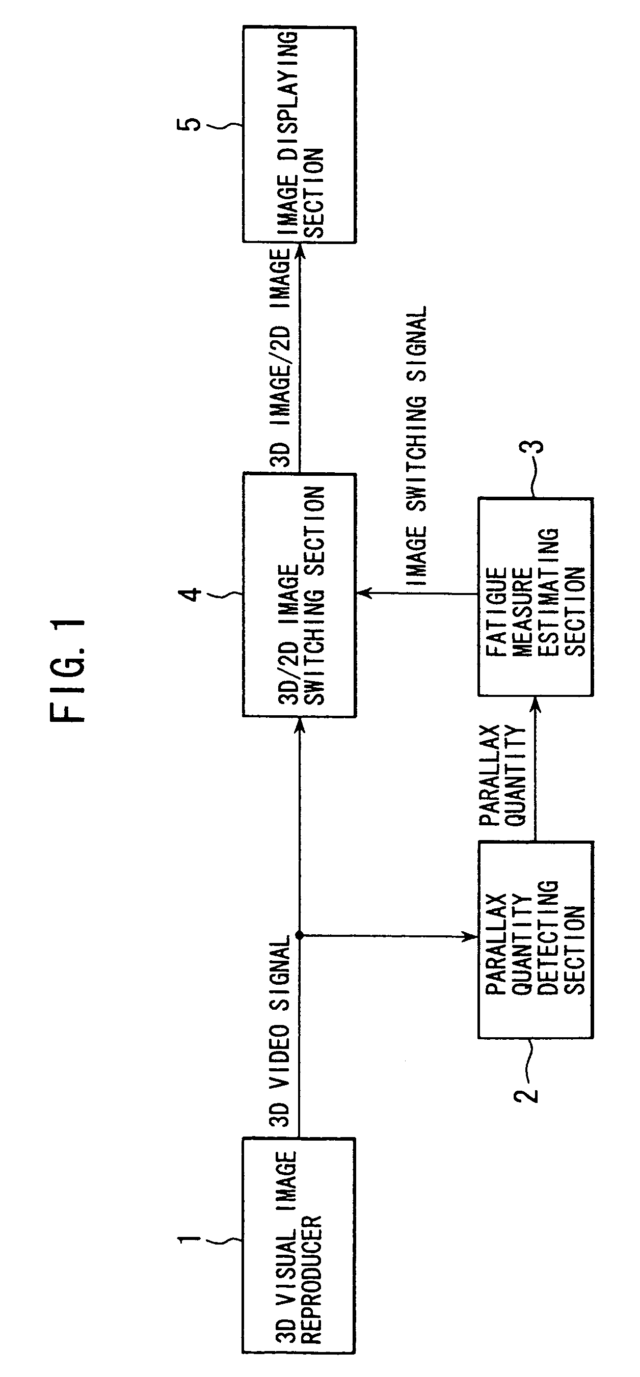
[0028]Some embodiments will now be described. FIG. 1 is a schematic block diagram showing a first embodiment of the visual image system according to the present invention. Referring to FIG. 1: what is denoted by numeral 1 is a three-dimensional image reproducer for transmitting three-dimensional video signal; 2, a parallax quantity detecting section for detecting a parallax quantity in three-dimensional video signal outputted from the three-dimensional image reproducer 1; 3, a fatigue measure estimating section for estimating a fatigue measure based on the parallax quantity detected at the parallax quantity detecting section 2; 4, a 3D / 2D image switching section for providing output by switching between three-dimensional video signal and two-dimensional video signal in accordance with an image switching signal which is provided on the basis of the estimation of fatigue measure; 5, an image display section for displaying a three-dimensional image or a two-dimensional image outputted ...


PUM


Abstract

A visual image system is constructed as including: a three-dimensional visual image reproducer for transmitting a three-dimensional video signal; a parallax quantity detecting section for detecting a parallax quantity in the three-dimensional video signal from the three-dimensional visual image reproducer; a fatigue measure estimating section for estimating the degree of fatigue based on the detected parallax quantity and outputting an image switching signal correspondingly to a fatigue measure estimating quantity; a 3D/2D image switching section for providing an output by switching between three-dimensional and two-dimensional images based on the image switching signal; and an image display section for displaying a three-dimensional image or a two-dimensional image. The visual image system thereby fulfills the capability of suitably controlling the degree of three-dimensionality of stereoscopic images by inferring from the inputted video signal the degree of effects likely to be produced on the observer.

Description

[0001]This application is a divisional of application Ser. No. 09 / 323,694 filed Jun. 2, 1999 now U.S. Pat. No. 6,614,927.BACKGROUND OF THE INVENTION[0002]The present invention relates to visual image systems and, more particularly, relates to a visual image system in which the degree of three-dimensionality is controlled by estimating effects produced on the observer based on video signals.[0003]Various proposals have been made with respect to visual image systems. For example, the following technique is disclosed in Japanese Patent Publication No.2594235 as that for converting two-dimensional visual image into three-dimensional visual image. In particular, a disclosure has been made with respect to a method for converting a two-dimensional visual image into a three-dimensional visual image in which the extent and direction of a horizontal motion in image is detected using a two-dimensional video signal by generating from the two-dimensional video signal a main video signal serving ...

Claims


Application Information

Patent Timeline
IPC IPC(8): G06K9/00G06T13/20H04N13/122
CPCH04N13/0011H04N13/0018H04N13/0033H04N13/0454H04N13/026H04N13/0055H04N13/0059H04N2213/002H04N13/0429H04N13/0456H04N2013/0081H04N2013/0085H04N13/194H04N13/189H04N13/111H04N13/122H04N13/144H04N13/332H04N13/359H04N13/361H04N13/261
Inventor TABATA, SEIICHIRO
Owner OLYMPUS CORP
Why Eureka
Try Eureka