Method of detecting displacement of exposure position marks

a technology of exposure position marks and displacement, which is applied in the direction of instruments, photomechanical equipment, and semiconductor/solid-state device details, etc., can solve the problems of inability to eliminate measurement fluctuations, aberration of the lenses used in the measurement optical system, and not always obtained same detection results, etc., to improve the precision with which displacement can be detected. , the effect of high precision

Inactive Publication Date: 2008-01-03
FUJITSU LTD
View PDF7 Cites 0 Cited by
  • Summary
  • Abstract
  • Description
  • Claims
  • Application Information

AI Technical Summary

Benefits of technology

[0014]Marks composed of the bar-shaped patterns shown in FIG. 6B are used to make it easier to recognize the mark positions compared to marks composed of square patterns, especially when the marks have a small thickness. However, even when the shape of the marks is changed in this way, it is still not possible to eliminate the fluctuations in the measurements due to the measurement apparatus, the thickness of the marks, and the like.
[0015]When manufacturing a semiconductor or a thin-film magnetic head, patterns are presently controlled at the nanometer level. In this way, when extremely high precision is required for positioning, it becomes necessary to also control fluctuations in measurements caused by the measurement method that conventionally did not cause a problem.
[0017]The present invention was conceived to solve the problem described above and it is an object of the present invention to provide a method of detecting a displacement of exposure position marks that can reliably recognize exposure position marks that enable the displacement to be detected and can correctly and efficiently detect the displacement of an exposure position based on measurement results produced by recognizing the marks.
[0022]According to the method of detecting a displacement of exposure position marks according to the present invention, when using exposure position marks where a first pattern and a second pattern are relatively positioned inside and outside one another, it is possible to calculate the displacement so as to cancel out fluctuations based on the relative positions of the first pattern and the second pattern, and therefore the displacement of the exposure position marks can be detected with high precision. By using a construction where patterns are disposed on two layers and disposing the patterns in a crisscross arrangement, it is possible to obtain the displacement as the average of the center positions of the patterns, thereby improving the precision with which the displacement can be detected.

Problems solved by technology

In reality however, the same detection result is not always obtained.
Such fluctuations can be caused by the shape of the patterns wherein it is not possible to properly detect edge parts and the like of the patterns when image recognition is carried out for the exposure position marks, and can also be due to unavoidable causes when measuring the exposure position marks.
Such unavoidable causes are thought to be (i) aberration of the lenses used in the measurement optical system, (ii) the exposure position marks having different positions in the height direction due to the marks formed in the former process and the latter process being formed at different positions in the laminating direction, and (iii) the shapes of the marks being recognized differently depending on the measurement direction due to the exposure position marks being formed with predetermined thicknesses.
However, even when the shape of the marks is changed in this way, it is still not possible to eliminate the fluctuations in the measurements due to the measurement apparatus, the thickness of the marks, and the like.

Method used


Image

  • Method of detecting displacement of exposure position marks
  • Method of detecting displacement of exposure position marks
  • Method of detecting displacement of exposure position marks

Examples


first embodiment

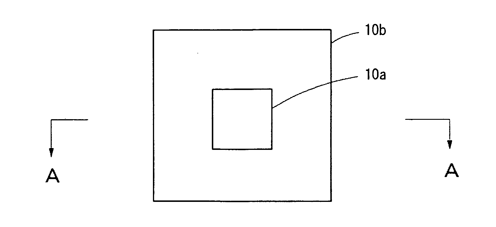
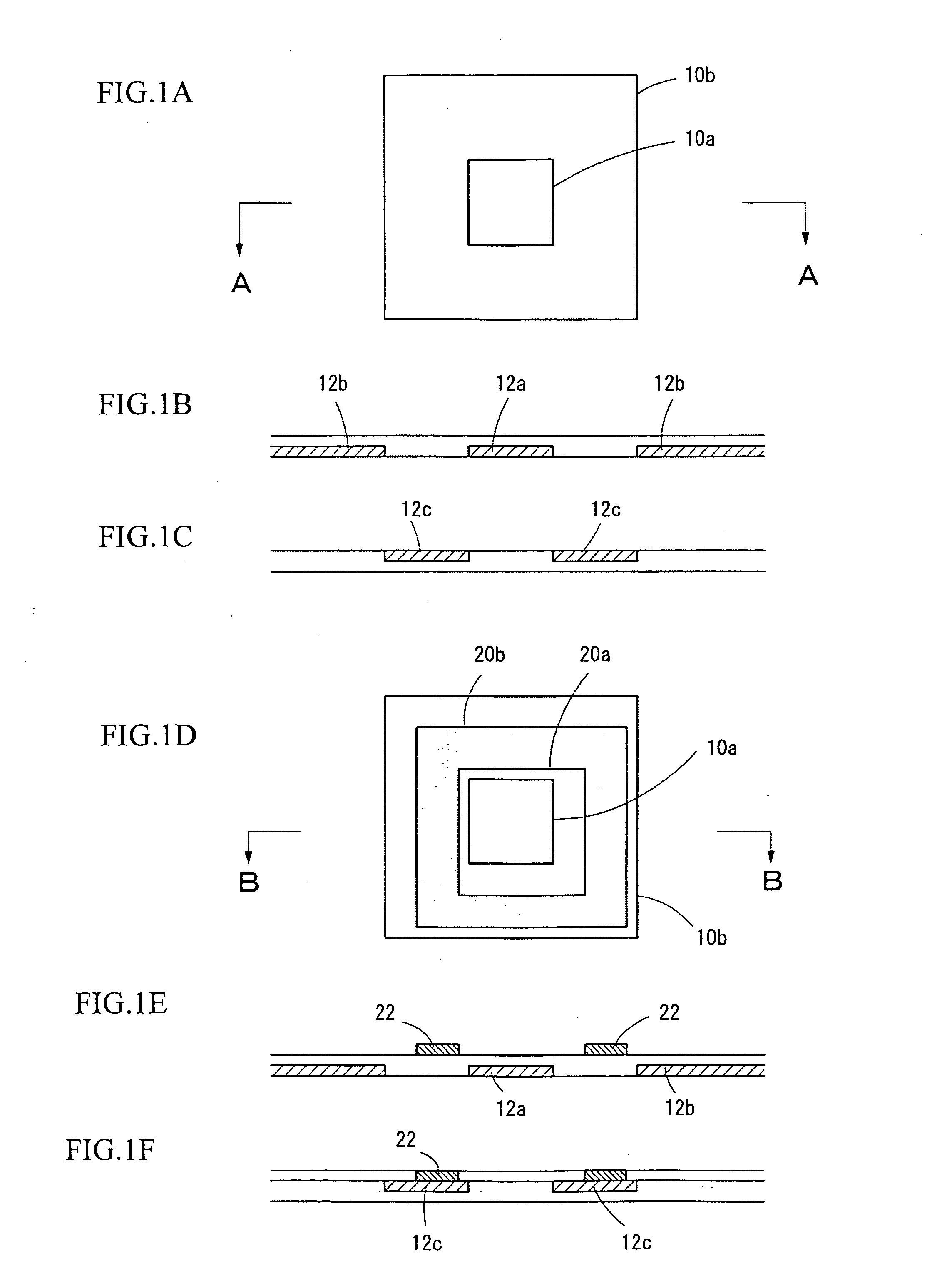
[0032]FIGS. 1A to 1F show examples of exposure position marks that are formed in a former process and in a latter process to enable displacement of the marks to be detected, according to the method of detecting displacement of exposure position marks according to the present invention.

[0033]FIG. 1A shows the exposure position marks formed in the former process. These exposure position marks are formed so that the center positions of two, (i.e., a large and a small) square patterns 10a and 10b match and are disposed so that the edges of the patterns 10a and 10b are parallel.

[0034]FIGS. 1B and 1C are cross-sectional views taken along the line A-A in FIG. 1A and show examples of where the square patterns 10a and 10b are formed on a base layer. FIG 1B shows an example where a pattern 12a that forms the inner square pattern 10a and a pattern 12b that forms the outer square pattern 10b are formed. FIG. 1C shows an example where a frame-shaped pattern 12c is formed on the base layer to for...

second embodiment

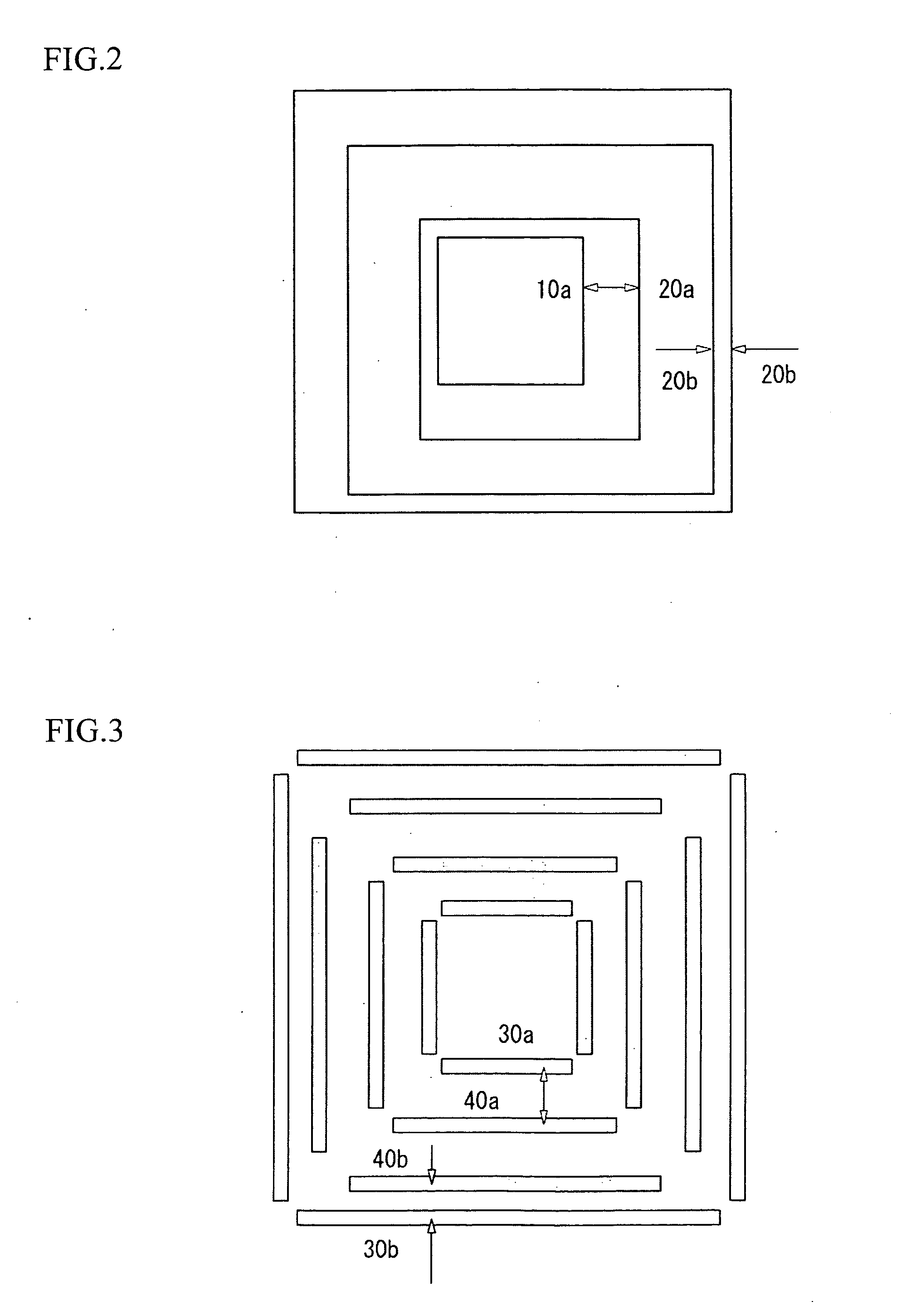
[0048]FIG. 3 shows another example of exposure position marks used by the method of detecting a displacement of exposure position marks according to the present invention. The exposure position marks used in the present embodiment are composed of bar-shaped patterns that are disposed in quadrangular arrangements where a quadrangular arrangement of bar-shaped patterns 30a on the inside and a quadrangular arrangement of bar-shaped patterns 30b on the outside are used as the first pattern and a quadrangular arrangement of bar-shaped patterns 40a on the inside and a quadrangular arrangement of bar-shaped patterns 40b on the outside are used as the second pattern.

[0049]The patterns 30a and 30b are formed in square arrangements so that the center positions of the respective quadrangular arrangements match and the edges of the arrangements are parallel. The patterns 40a and 40b are also formed in square arrangements so that the center positions of the respective quadrangular arrangements m...

third embodiment

[0052]FIG. 4 shows another example of exposure position marks used by the method of detecting a displacement of exposure position marks according to the present invention. The exposure position marks in the present embodiment are an example where square patterns 50a and 50b that are the first pattern and square patterns 60a and 60b that are the second pattern are formed with the same shape and the same size and are disposed in a crisscross arrangement.

[0053]The first pattern and the second pattern are exposure position marks that are formed in different steps. The first pattern and the second pattern are formed so that the center of respective center positions of the square patterns 50a and 50b that are the first pattern and the center of the respective center positions of the square patterns 60a and 60b that are the second pattern match.

[0054]When detecting the displacement, image recognition is carried out for the square patterns 50a and 50b that form the first pattern and the squ...


PUM


Abstract

Exposure position marks are reliably recognized and the displacement of an exposure position is correctly and efficiently detected based on measurement results produced by recognizing the marks. The exposure position marks are constructed of a first pattern made up of an inner quadrangular pattern and an outer quadrangular pattern and a second pattern shaped as a rectangular frame whose inner edge and outer edge are formed as quadrangular patterns. The first pattern and the second pattern are formed with an intention of making center positions of the first pattern and the second pattern match and of having the second pattern disposed inside a region between an inner quadrangular pattern and an outer quadrangular pattern of the first pattern. The displacement of the exposure position is found by calculating an average of a measurement produced by detecting a displacement between the center positions of the inner quadrangular pattern of the first pattern and the quadrangular pattern that is the inner edge of the second pattern and a measurement produced by detecting a displacement between the center positions of the outer quadrangular pattern of the first pattern and the quadrangular pattern that is the outer edge of the second pattern

Description

BACKGROUND OF THE INVENTION[0001]1. Field of the Invention[0002]The present invention relates to a method of detecting displacement of exposure position marks, which are provided for detecting displacement of an exposure position, during the manufacturing of a semiconductor or a thin-film magnetic head.[0003]1. Related Art[0004]When manufacturing a semiconductor, a thin-film magnetic head, or the like, a required conductive pattern or insulating layer pattern is formed by photolithography. During the manufacturing of such devices, when laminating a conductive pattern or insulating layer pattern, displacement of the pattern is detected, it is judged whether the exposure position is within a tolerated range, and the displacement is fed back to the exposure apparatus so that the exposure operation can be carried out with high precision.[0005]Displacement of exposure position marks is detected by forming the exposure position marks at positions that do not affect the products, such as a...

Claims


Application Information

Patent Timeline
Patent Type & Authority Applications(United States)
IPC IPC(8): G01B11/00
CPCG03F7/70633G03F7/20
Inventor FUJITA, MUTSUMI
Owner FUJITSU LTD
Why Eureka
Try Eureka