Tracer gas airflow measurement system with high turndown ratio

a technology of airflow measurement and turndown ratio, which is applied in the direction of measurement devices, instruments, structural/machine measurement, etc., can solve the problems of cumbersome design of tracer gas airflow measurement system, limited to measuring a relatively narrow band of airflow rate with high accuracy, and inability to use, so as to avoid damage to sensors, valve control structures and other system components. , the effect of high accuracy

Active Publication Date: 2017-05-25
RGT UNIV OF CALIFORNIA
View PDF3 Cites 1 Cited by
  • Summary
  • Abstract
  • Description
  • Claims
  • Application Information

AI Technical Summary

Benefits of technology

[0015]The present technology pertains to tracer gas airflow measurement systems that allow continuous sustained high accuracy measurements of airflow across a very wide range of flow rates in a variety of scenarios. Traditional designs for tracer gas airflow measurements systems are cumbersome, can only be used in certain circumstances, and they are limited to measuring a relatively narrow band of airflow rates with high accuracy. The present technology, with the ability to add enthalpy to the tracer gas, allows for measurement of any possible range of airflow in ductwork with a better than 2% accuracy due to the continuous and sustained flow of tracer gas provided by the injector apparatus without operating at sub-freezing temperatures. Therefore, exterior ice formation, ice blockages or restrictions in the interior valve channels and damage to sensors, valve control structures and other system components can be avoided.
[0016]The present technology is able to measure such a wide range of airflows through the scalability of each component or the ability to use multiple modules simultaneously.
[0017]In a preferred embodiment, the tracer gas airflow measurement system vaporizes liquid CO2 (by allowing phase change within a standard CO2 cylinder), heats the CO2 vapor isobarically at high pressure >100 psi, expands the hot gas across a pressure regulator to a lower working pressure (>30 psi), and then modulates gas flow using a mass flow controller with a high turndown ratio. The CO2 tracer flow may be injected into an airflow volume using various injection devices and the CO2 concentration can then be measured downstream. The apparatus design allows for large CO2 flow rates and continuous and sustained CO2 flows while also avoiding operation at very cold temperatures that will damage the system components. The controlled and variable heating of high a pressure CO2 gas flow before the gas regulator allows all points in the system to remain above freezing, and within a safe temperature range.
[0018]The advantage of the technology is in its ability to conduct continuous and sustained measurements, in a variety of applications, over a range of airflow rates. Although carbon dioxide is used as a tracer gas to illustrate the apparatus, other tracer gases may be adapted for use in a variety of settings.

Problems solved by technology

Traditional designs for tracer gas airflow measurements systems are cumbersome, can only be used in certain circumstances, and they are limited to measuring a relatively narrow band of airflow rates with high accuracy.

Method used


Image

  • Tracer gas airflow measurement system with high turndown ratio
  • Tracer gas airflow measurement system with high turndown ratio
  • Tracer gas airflow measurement system with high turndown ratio

Examples


example

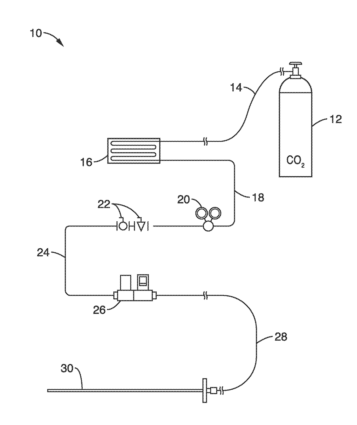
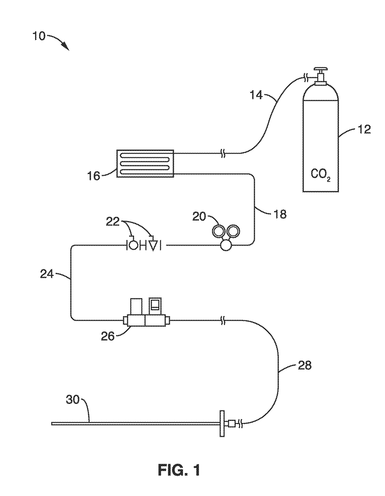
[0047]In order to demonstrate the technology, an apparatus as shown in FIG. 1 was assembled. The tracer gas injector was set up to operate with a high pressure (˜800 psi) gas cylinder. The gas was heated to approximately 100° F. before going through the pressure regulator. The pressure regulator dropped the heated tracer gas pressure to around 125 psi and the temperature of the gas dropped to approximately 90° F.

[0048]The CO2 tracer gas was injected into a test duct 10 inches downstream of an upstream flow straightener throughout the cross sectional area of the duct with a tubing tree with 40 injection points to distribute the CO2 tracer gas. The bulk airflow moving through the duct was sampled 2 feet downstream of the downstream flow straightener through an 8 point space average aspirated array.

[0049]Tests were run at 3 different airflows: 3100, 4000, and 5000 CFM. In this operating range, the accuracy of the nozzle box is ±0.5% of the reading. All tests agreed within the uncertain...


PUM


Abstract

A gas injector apparatus and method for use with a tracer gas airflow measurement system that allows for large, continuous tracer gas flow rates while avoiding operation at very cold temperatures that will damage equipment. The controlled and variable heating of high pressure tracer gas flow before a gas regulator allows all points in the system to remain above freezing, and within a safe temperature range. The system has a tracer gas source and a heater that heats the gas isobarically at high pressure (>100 psi) and the hot gas is expanded across a pressure regulator to a lower working pressure to ˜30 psi. The gas flow is modulated using a mass flow controller with a high turndown ratio and injected into a bulk fluid flow with an injector.

Description

CROSS-REFERENCE TO RELATED APPLICATIONS[0001]This application is a 35 U.S.C. §111(a) continuation of PCT international application number PCT / US2015 / 029545 filed on May 6, 2015, incorporated herein by reference in its entirety, which claims priority to, and the benefit of, U.S. provisional patent application Ser. No. 61 / 989,352 filed on May 6, 2014, incorporated herein by reference in its entirety. Priority is claimed to each of the foregoing applications.[0002]The above-referenced PCT international application was published as PCT International Publication No. WO 2015 / 171821 on Nov. 12, 2015, which publication is incorporated herein by reference in its entirety.STATEMENT REGARDING FEDERALLY SPONSORED RESEARCH OR DEVELOPMENT[0003]Not ApplicableINCORPORATION-BY-REFERENCE OF COMPUTER PROGRAM APPENDIX[0004]Not ApplicableBACKGROUND[0005]1. Technical Field[0006]The present technology pertains generally to tracer airflow measurement systems, and more particularly to a tracer gas injection...

Claims


Application Information

Patent Timeline
Patent Type & Authority Applications(United States)
IPC IPC(8): G01M3/22
CPCG01M3/22G01M3/205G01M3/222G01F1/704G01F15/10G01M3/223G01F1/708
Inventor WOOLLEY, JONATHANMODERA, MARKMANDE, CATON
Owner RGT UNIV OF CALIFORNIA
Why Eureka
Try Eureka