Positioning device for a reel

a technology of positioning device and reel, which is applied in the direction of electrical cable installation, telephone set construction, and relatively moving parts of cable arrangements, etc. it can solve the problems of failure of positioning, high cost of fabrication, and difficult fabrication of molds for such structures, and achieve easy and fast installation, precise pulling or pulling of wires or cables

Active Publication Date: 2006-02-14
HUANG KUI HSIEN
View PDF7 Cites 96 Cited by
  • Summary
  • Abstract
  • Description
  • Claims
  • Application Information

AI Technical Summary

Benefits of technology

[0008]Still another object of the present invention is to provide a positioning device for a reel, wherein appropriate length after pulled or retracted could be secured precisely.
[0010]Yet another object of the present invention is to provide a positioning device for a reel, wherein the pulling or retraction of wire / or cable is quick and simple and the wire or cable can be pulled or retracted in one step or in multiple steps.
[0011]Still a further object of the present invention is to provide a positioning device for a reel, wherein the assembly can be easily and quickly installed.

Problems solved by technology

The conventional structure requires very precise dimension and therefore fabrication of a mold for such structure is difficult, and the cost of fabrication is high.
Further, the wear of the rail A31 or the big gap formed on the rail A31 will cause a failure in positioning.
Therefore, the conventional reel A10 is frequently dislocated or cannot be positioned.
In addition, the steel bead used for positioning will not allow step by step retraction of the wire, the positioning of the wire is not accurate and only one round is made, otherwise positioning is not possible.
This will cause either the cable is too long or too short.

Method used


Image

  • Positioning device for a reel
  • Positioning device for a reel
  • Positioning device for a reel

Examples


Embodiment Construction

[0024]The following descriptions are of exemplary embodiments only, and are not intended to limit the scope, applicability or configuration of the invention in any way. Rather, the following description provides a convenient illustration for implementing exemplary embodiments of the invention. Various changes to the described embodiments may be made in the function and arrangement of the elements described without departing from the scope of the invention as set forth in the appended claims.

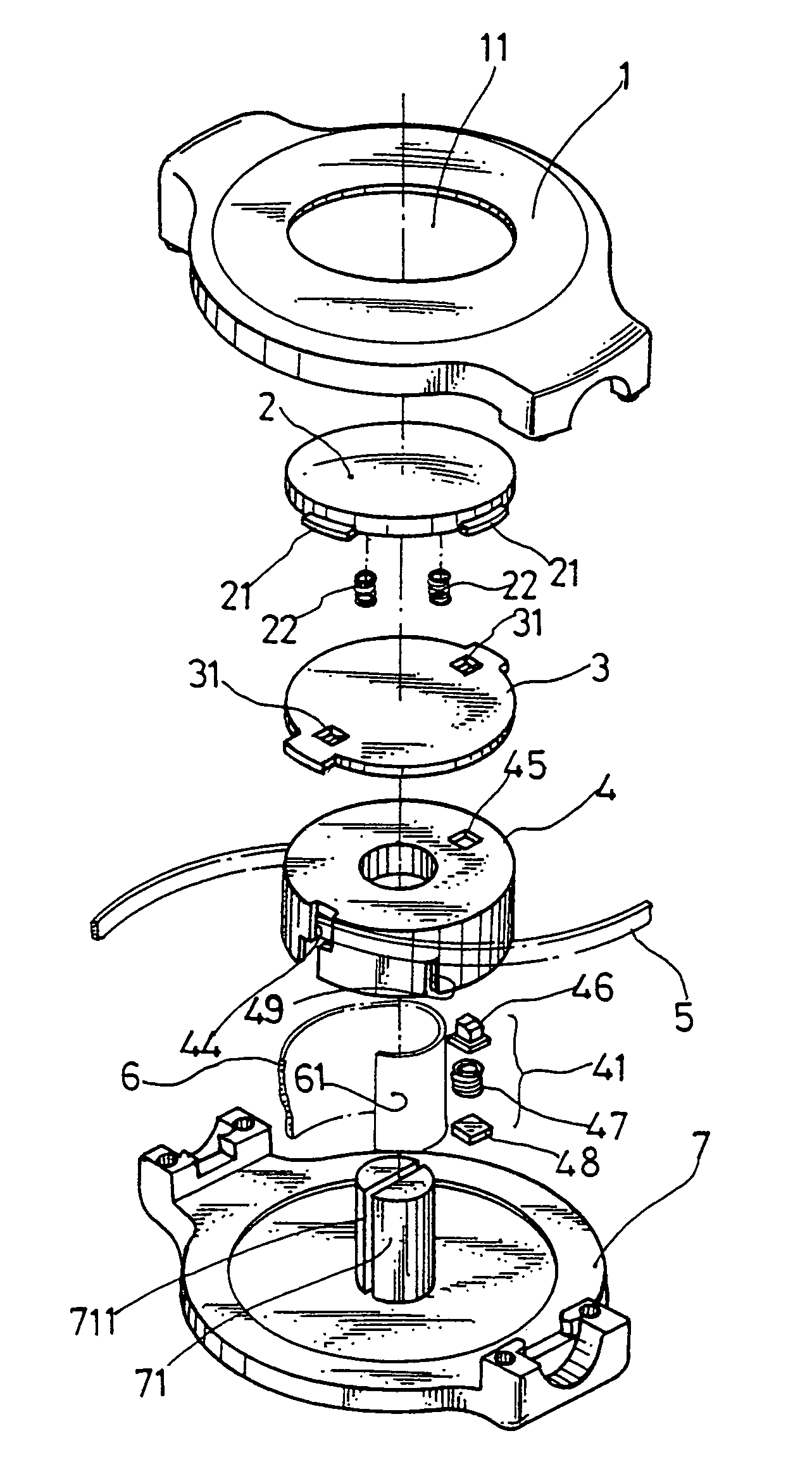
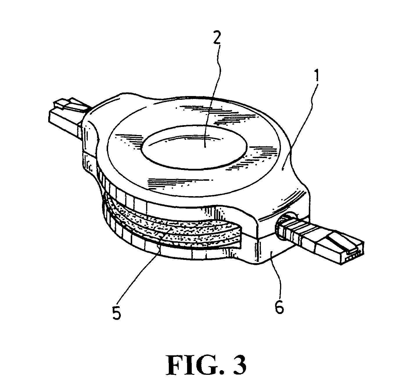
[0025]Referring to FIGS. 3 and 4, the positioning device for a reel operated with button comprising a top cover 1, a press button 2, a partition plate 3, a rotating plate 4, a wire 5, a rotating spring 6 and a bottom cover 7, wherein the top cover 1 is provided with a center hole 11 similar to the press button 2 for the mounting of the press button 2. As shown in FIG. 5, the bottom inner edge of the center hole 11 is provided with the first level 111 and a second stepped level 113. The first step...


PUM


Abstract

A positioning device for a reel is disclosed. The positioning device contains a spring-loaded reeling disc, wherein when the cable or wire is pulled to rotate for a half round, a positioning mechanism is made. A button is used to control either a single step or multiple steps retraction of the cable or wire.

Description

BACKGROUND OF THE INVENTION[0001](a) Technical Field of the Invention[0002]The present invention relates to a reel for cable-reeling or wire-reeling, and in particular to a positioning device for a reel. The reel allows cable or wire to be retracted to the reel neatly.[0003](b) Description of the Prior Art[0004]FIGS. 1 and 2 show a conventional reel A10 comprising a front cover A1, a rotating spring A2, a sliding seat A3, a transmission wire A4, a positioning bead A5 and a rear cover A6. The rotating spring retracts the transmission wire A4 and a positioning mechanism employing the steel bead A5 to position the wire A4. A steel bead rail A31 is provided to allow the movement of the steel bead A5. The conventional structure requires very precise dimension and therefore fabrication of a mold for such structure is difficult, and the cost of fabrication is high. Further, the wear of the rail A31 or the big gap formed on the rail A31 will cause a failure in positioning. Therefore, the co...

Claims


Application Information

Patent Timeline
Patent Type & Authority Patents(United States)
IPC IPC(8): B65H75/48
CPCB65H75/4431
Inventor HUANG, KUI-HSIEN
Owner HUANG KUI HSIEN
Why Eureka
Try Eureka