Golf club and method of manufacturing

a golf club and manufacturing method technology, applied in the field of golf clubs, can solve the problems of complex fixture, need for specialized heat activated bonding agents, and difficulty in manufacturing the slot in the shaft tip, and achieve the effect of precisely located pins transversely mounted within the hosel bor

Inactive Publication Date: 2006-02-14
KARSTEN MFG CORP
View PDF7 Cites 20 Cited by
  • Summary
  • Abstract
  • Description
  • Claims
  • Application Information

AI Technical Summary

Problems solved by technology

Disadvantages of the foregoing method include the requirement for specialized heat activated bonding agents and the necessity of a complicated fixture.
Disadvantages of the aforementioned assembly may include the cost of manufacturing the slot in the shaft tip as well as the need for a precisely located pin transversely mounted within the hosel bore.
Although this method provides excellent alignment between the club head and shaft without complicated alignment fixtures or expensive custom shaft arrangements, it does have one drawback.
The statistical distribution about the minimum and maximum tolerances improves yield over the print tolerances, however, manufacturing tolerances do create a not-insignificant number of clubs that are rejected because either the interference is too great for the shaft to be assembled to the club or there is unacceptable clearance between the shaft and the hosel bore.
Reducing the tolerances and / or selectively fitting maximum material shafts to minimum material bores and vice versa improves yield, however, there is a cost associated with these manufacturing techniques.

Method used


Image

  • Golf club and method of manufacturing
  • Golf club and method of manufacturing
  • Golf club and method of manufacturing

Examples


Embodiment Construction

[0014]The drawing figures are intended to illustrate the general manner of construction and are not necessarily to scale. In the description and in the drawing figures, specific illustrative examples are shown and herein described in detail. It should be understood, however, that the drawing figures and detailed description are not intended to limit the invention to the particular form disclosed but are merely illustrative and intended to teach one of ordinary skill how to make and / or use the invention claimed herein and for setting forth the best mode for carrying out the invention.

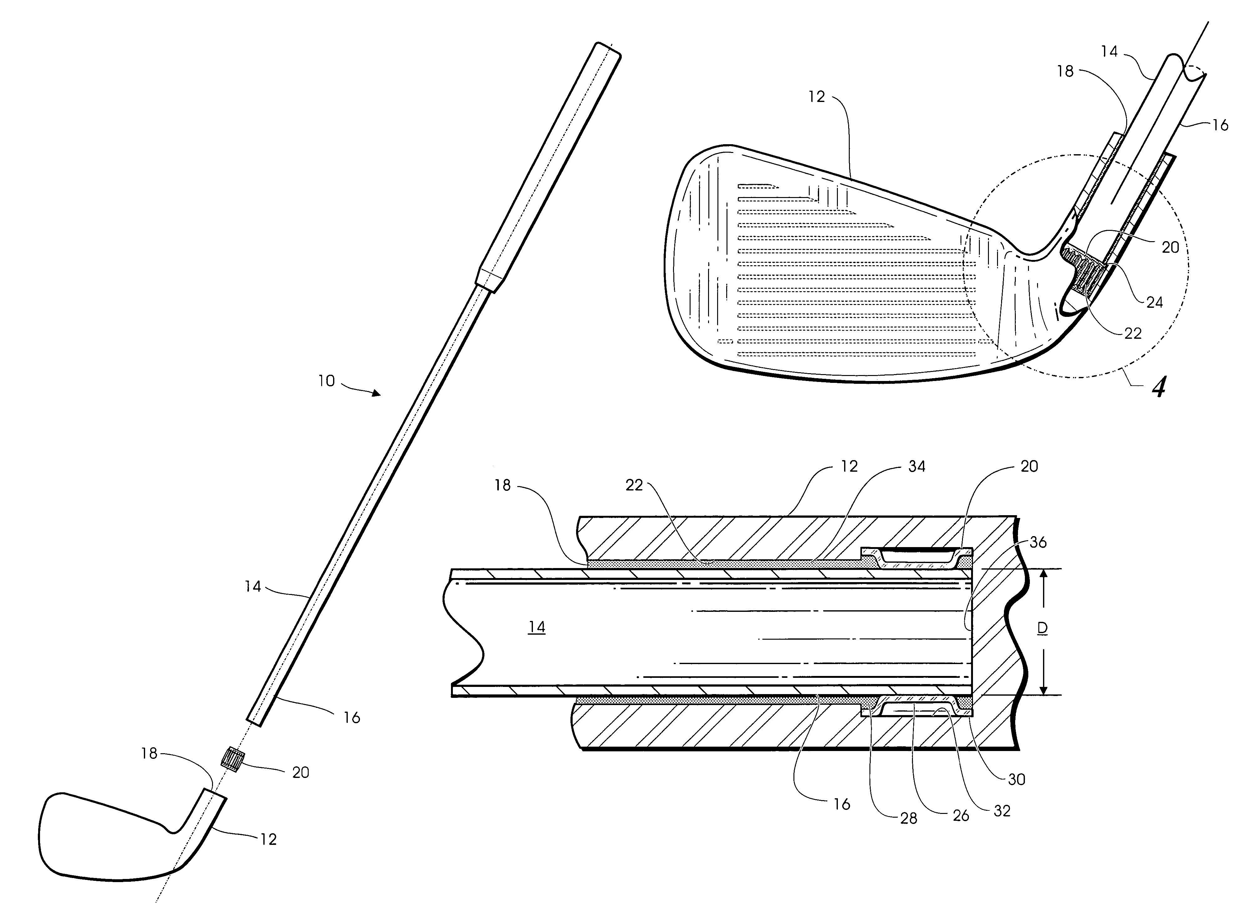
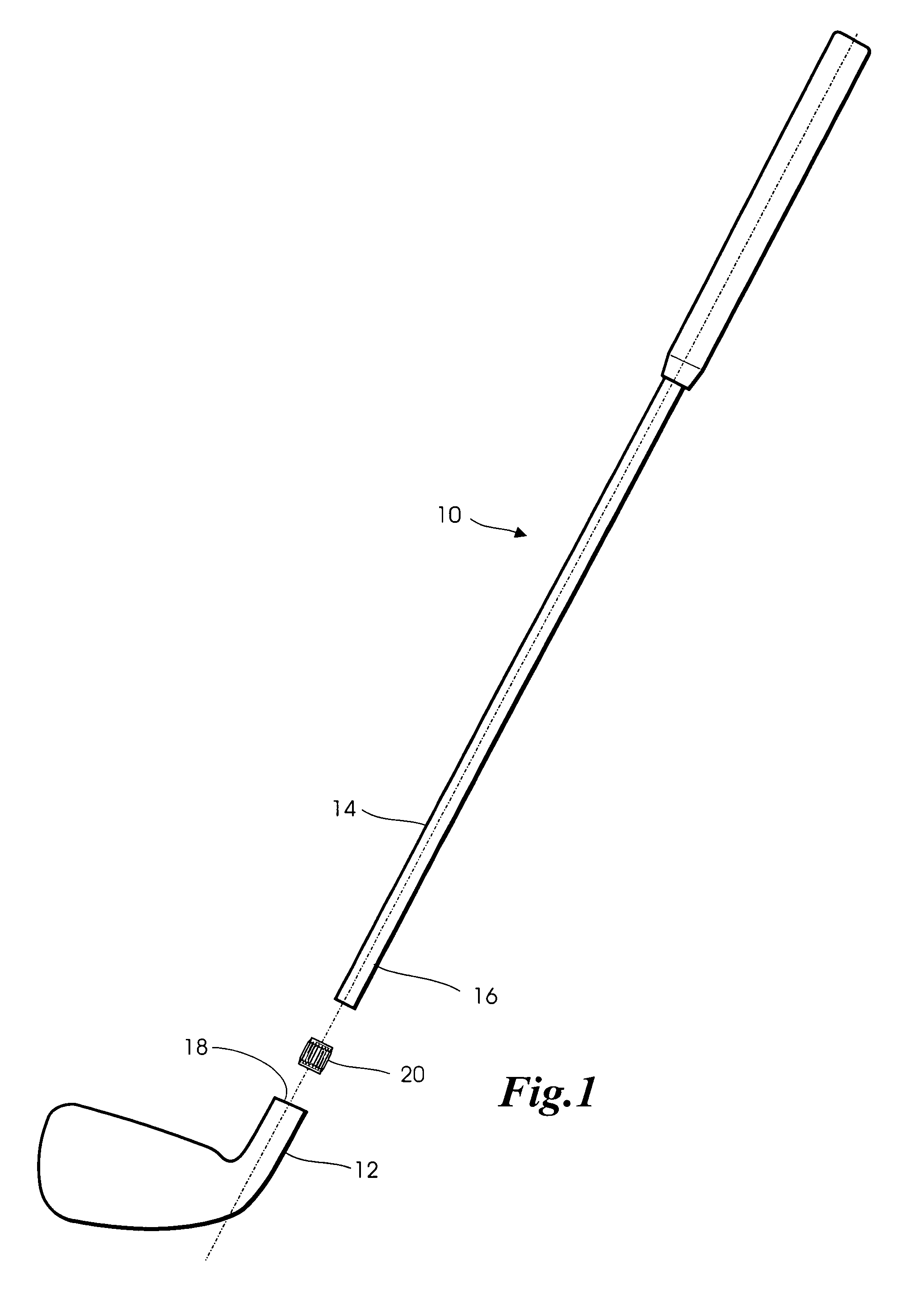
[0015]With reference to FIG. 1, a golf club 10 incorporating features of the present invention comprises a golf club head 12 and a golf club shaft 14. Golf club 10 is assembled by inserting the tip end 16 of golf club shaft 14 into the hosel bore 18 of golf club head 12. Prior to inserting tip end 16 into hosel bore 18, tip end 16 is coated with an adhesive, preferably an epoxy such as Hysol 10C Grey (no...


PUM

PropertyMeasurementUnit
diameteraaaaaaaaaa
widthaaaaaaaaaa
heightaaaaaaaaaa

Abstract

A golf club is manufactured according to a method in which a radially compliant crush sleeve is interposed between the shaft tip and hosel of the club head. The crush sleeve is fabricated from a strip of metal formed into a substantially cylindrical metallic band with a plurality of radially-extending dimples or corrugations that grip the shaft. The crush sleeve is retained either in an undercut region in the hosel bore, on a mandrel extending from the hosel, or on a pilot shaft at the tip of the golf club shaft. After the interface between the shaft and hosel is coated with an adhesive, the shaft is assembled to the hosel with the crush sleeve squeezed in between. The crush sleeve secures the shaft to the club head with sufficient rigidity to allow the adhesive to set while maintaining the appropriate axial and rotational alignment.

Description

BACKGROUND OF THE INVENTION[0001]This invention relates generally to golf clubs and more particularly to the assembly of golf club heads to golf club shafts.[0002]A critical step in the manufacture of golf clubs is the assembly of the club head to the club shaft. Typically, to achieve a suitably secure bond between the club head and the shaft, an epoxy adhesive is applied to the shaft and / or the hosel bore. The shaft is then inserted into the hosel bore and the adhesive on the joint is allowed to cure. Since the alignment between the longitudinal axis of the golf club shaft and the club head is critical, various methods and apparatus have been proposed for maintaining the alignment between the club shaft and the club head while the adhesive is curing.[0003]U.S. Pat. No. 5,771,552 to Karner, et al. discloses an apparatus comprising a plurality of clamps used to hold the club head and shaft in alignment. A heat-activated epoxy is applied to the joint, which is thereafter heated by mea...

Claims


Application Information

Patent Timeline
Patent Type & Authority Patents(United States)
IPC IPC(8): A63B53/02B29C65/54
CPCA63B53/02A63B60/00
Inventor NAYLOR, ROBERT F.PETERSEN, DAVID L.
Owner KARSTEN MFG CORP
Why Eureka
Try Eureka