Fluid transfer holder assembly and a method of fluid transfer

a technology of fluid transfer holder and holder, which is applied in the field of collection of biological fluid specimens, can solve the problems of not being able to support the portion of the blood collection tube that has passed through the central opening of the holder, and achieve the effect of preventing inadvertent disengagemen

Active Publication Date: 2006-02-14
SMITHS MEDICAL ASD INC
View PDF10 Cites 65 Cited by
  • Summary
  • Abstract
  • Description
  • Claims
  • Application Information

AI Technical Summary

Benefits of technology

[0007]The non-continuous wall is made of adjacent sections. The diameter of the circumferential wall is such that it is slightly smaller than the diameter of the proximal portion of the holder. At each section of the wall there is formed a protuberance at its exterior. These protuberances, or fingers, will mate to a groove that is formed at the inner surface of the proximal portion of the cylindrical member, when the adapter is fitted to the member. With the protuberances mated to the internal groove, the adapter and the member are prevented from being inadvertently disengaged from each other, once the adapter is inserted to the member.

Problems solved by technology

The problem of the '425 prior art device is that the only thing that guides the insertion of the tube to the collection cup is the circumferential lip of the central opening of the cap through which the vacuum tube passes.
Moreover, there is nothing to support the portion of the blood collection tube that has passed through the central opening of the cap, before the rubber stopper is pierced by the cannula inside the collection cup.

Method used


Image

  • Fluid transfer holder assembly and a method of fluid transfer
  • Fluid transfer holder assembly and a method of fluid transfer
  • Fluid transfer holder assembly and a method of fluid transfer

Examples


Embodiment Construction

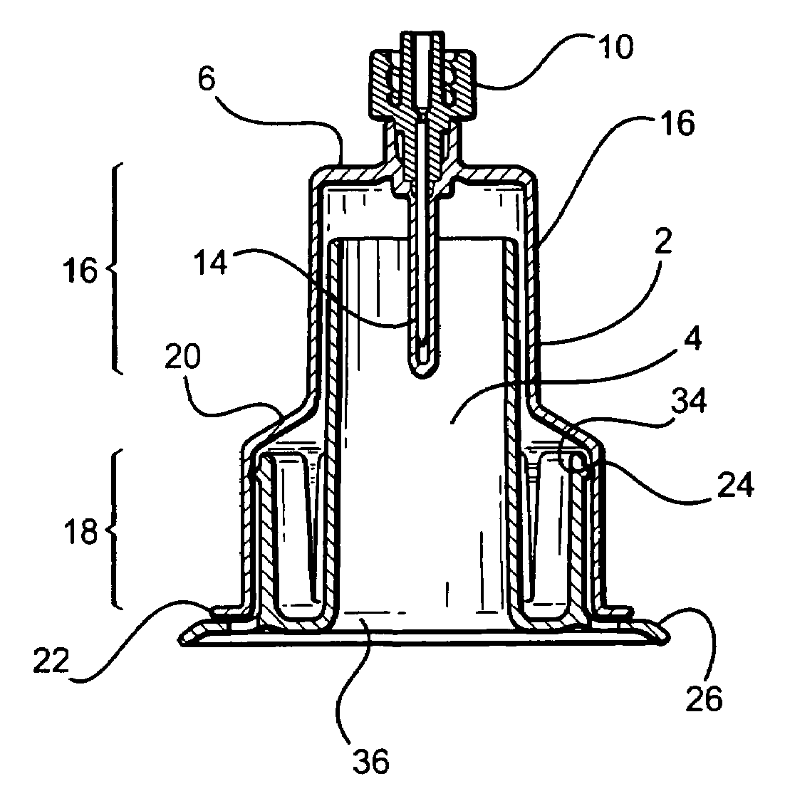
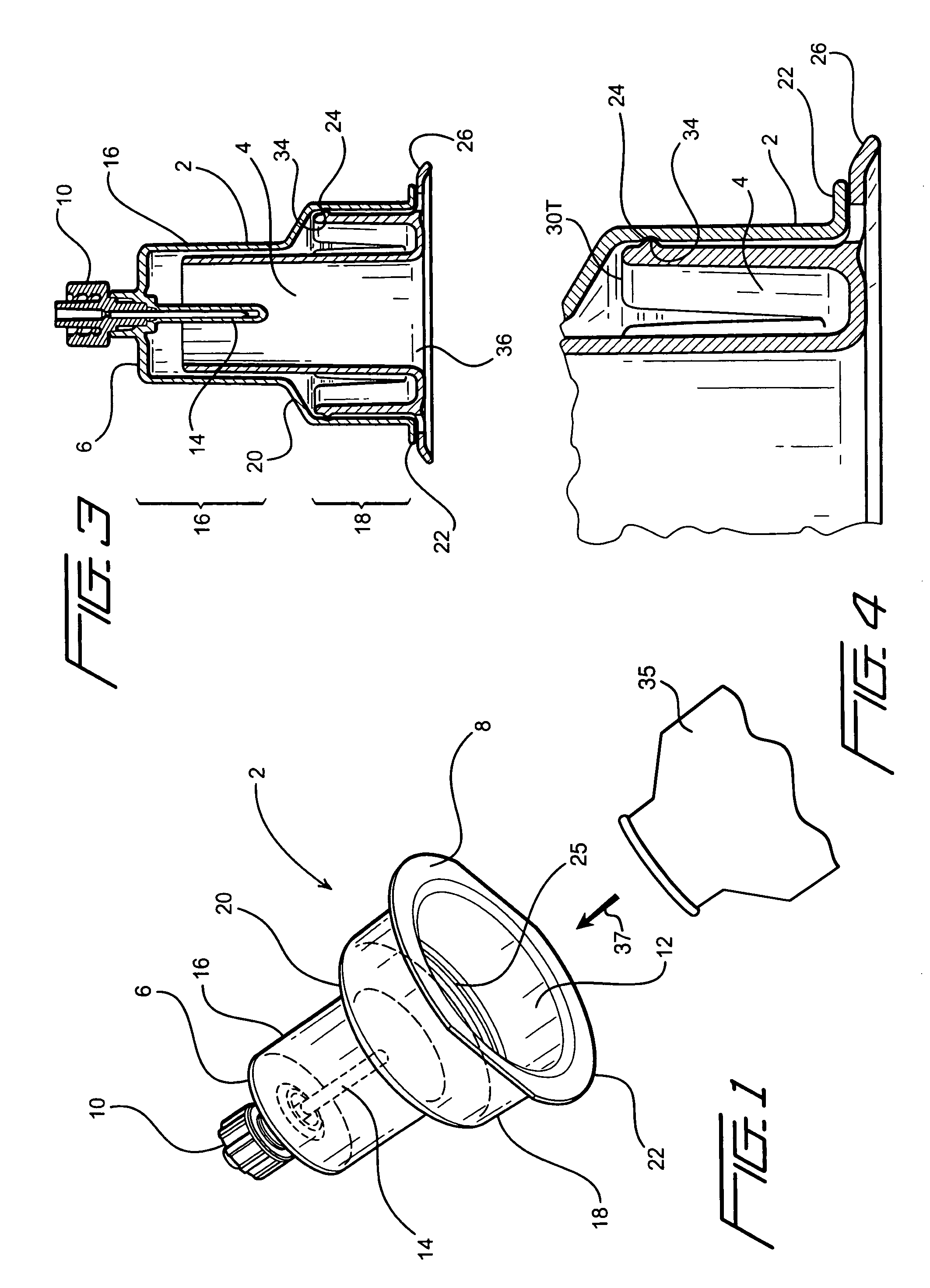
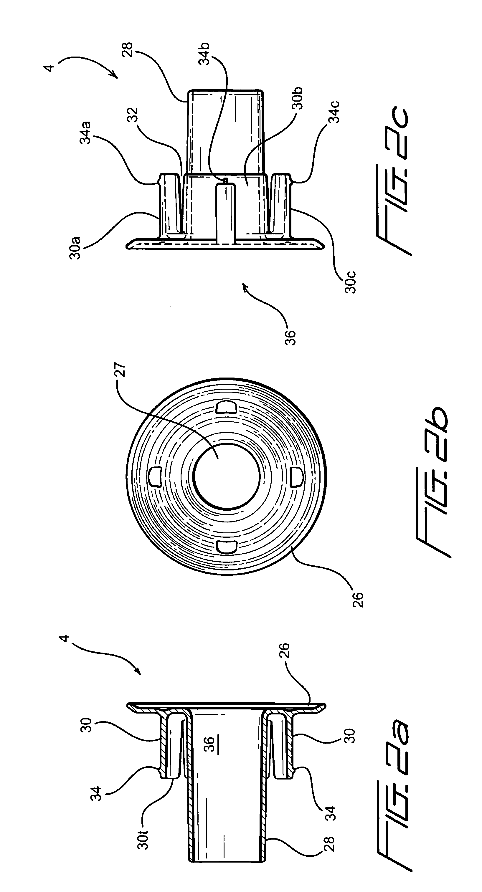
[0015]With reference to FIGS. 1 and 2a–2c, the fluid transfer system of the instant invention is shown to include a holder member 2 and an adapter member 4. Holder member 2 is a cylindrical member having a closed end 6 and an open end 8. Closed end 6 is fitted with a luer 10 that is matable with a luer of a syringe or an intravenous needle, as is well known in the art. Open end 8 has an opening 12 through which adapter member 4 may be inserted to the interior of holder member 2. A cannula or needle 14, shown covered by a rubber boot or shroud, extends into the interior of holder member 2 for establishing a fluid pathway from luer 10 to the interior of holder member 2.

[0016]Holder member 2 comprises a distal portion 16 and a proximal portion 18. Distal portion 16 has a diameter or cross section that is smaller than the diameter or cross section of proximal portion 18. As best shown in FIG. 3, distal portion 16 is joined to proximal portion 18 by a shoulder 20 that slopes from distal ...


PUM


Abstract

A fluid transfer system has a holder that is made of a cylindrical member having a closed end and an open end. The closed end has fitted thereto a luer and a cannula that extends into the interior of the holder. The holder has a distal portion that has a first cross section and a proximal portion that has a second cross section. The cross section of the distal portion is smaller than the cross section of the proximal portion. The distal and proximal portions are joined by a shoulder. The fluid transfer system also includes an adapter that is inserted to the holder from the open end of the holder. The adapter has a base having a central opening and a cylindrical tube that extends from the central opening. The diameter of the cylindrical tube is slightly smaller than the diameter of the distal portion and is configured to accept a first type of fluid collection store such as a vacuum tube. With the adapter removed, the holder can accept a differently dimensioned fluid collection store such as for example a blood culture collection bottle.

Description

FIELD OF THE INVENTION[0001]The instant invention relates to the collection of biological fluid specimens and particularly the collection of bodily fluids such as for example blood from a patient and the transfer of the bodily fluid from the patient to differently dimensioned fluid storage bottles or tubes.BACKGROUND OF THE INVENTION[0002]The bodily fluid from a patient, for example blood, is usually withdrawn from a patient and stored in either a vacuum tube or a blood culture collection bottle. To collect blood into a vacuum tube, conventionally a Vacutainer holder into which a vacuum tube may be inserted is used. In particular, a double-ended needle is threadingly mated to the Vacutainer holder, the patient is pricked with the end of the needle that extends from the Vacutainer holder, after which a vacuum tube is inserted to the Vacutainer holder so that its closure rubber stopper is pierced by the other of the double-ended needle. Blood from the vein of the patient then flows in...

Claims


Application Information

Patent Timeline
Patent Type & Authority Patents(United States)
IPC IPC(8): A61B19/00A61B10/00B67D99/00A61J1/00A61J1/20
CPCA61J1/2096A61B10/0045Y10S604/905A61J2001/2055A61J2001/201A61J1/201A61J1/2055
Inventor SIMAS, JR., ROBERTMACLEAN, DAVID
Owner SMITHS MEDICAL ASD INC
Why Eureka
Try Eureka