
Standoff/mask structure for electrical interconnect

a technology of standoff/mask structure and electrical interconnection, which is applied in the direction of conductive pattern formation, transportation and packaging, lithography/patterning, etc., can solve the problems of difficult to reliably and efficiently mechanically and electrically interconnect circuit structures

Active Publication Date: 2006-02-14
XEROX CORP
View PDF5 Cites 10 Cited by
  • Summary
  • Abstract
  • Description
  • Claims
  • Application Information

AI Technical Summary

Benefits of technology

The patent text describes techniques for interconnecting circuit structures, which can be difficult and inefficient. The invention provides a method for efficiently interconnecting circuit structures using a patterned standoff structure and a laminate mask structure. The patterned standoff structure includes a plurality of conductive islands or bumps that are surrounded by an adhesive layer. The laminate mask structure includes a mask adhesive layer and a mask liner layer that can be used to create a patterned standoff structure. The invention allows for reliable and efficient mechanical and electrical interconnection of circuit structures.

Problems solved by technology

Circuit structures such as circuit boards, integrated circuit die, and circuit packages are mechanically and / or electrically interconnected by a variety of techniques and it can be difficult to reliably and efficiently mechanically and electrically interconnect circuit structures.

Method used


Image

  • Standoff/mask structure for electrical interconnect
  • Standoff/mask structure for electrical interconnect
  • Standoff/mask structure for electrical interconnect

Examples


Embodiment Construction

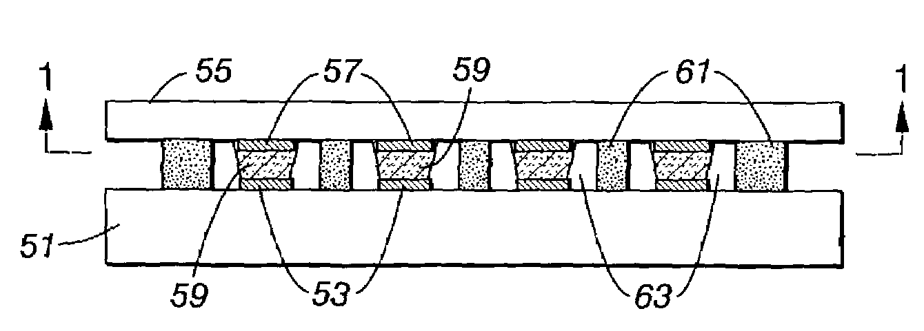
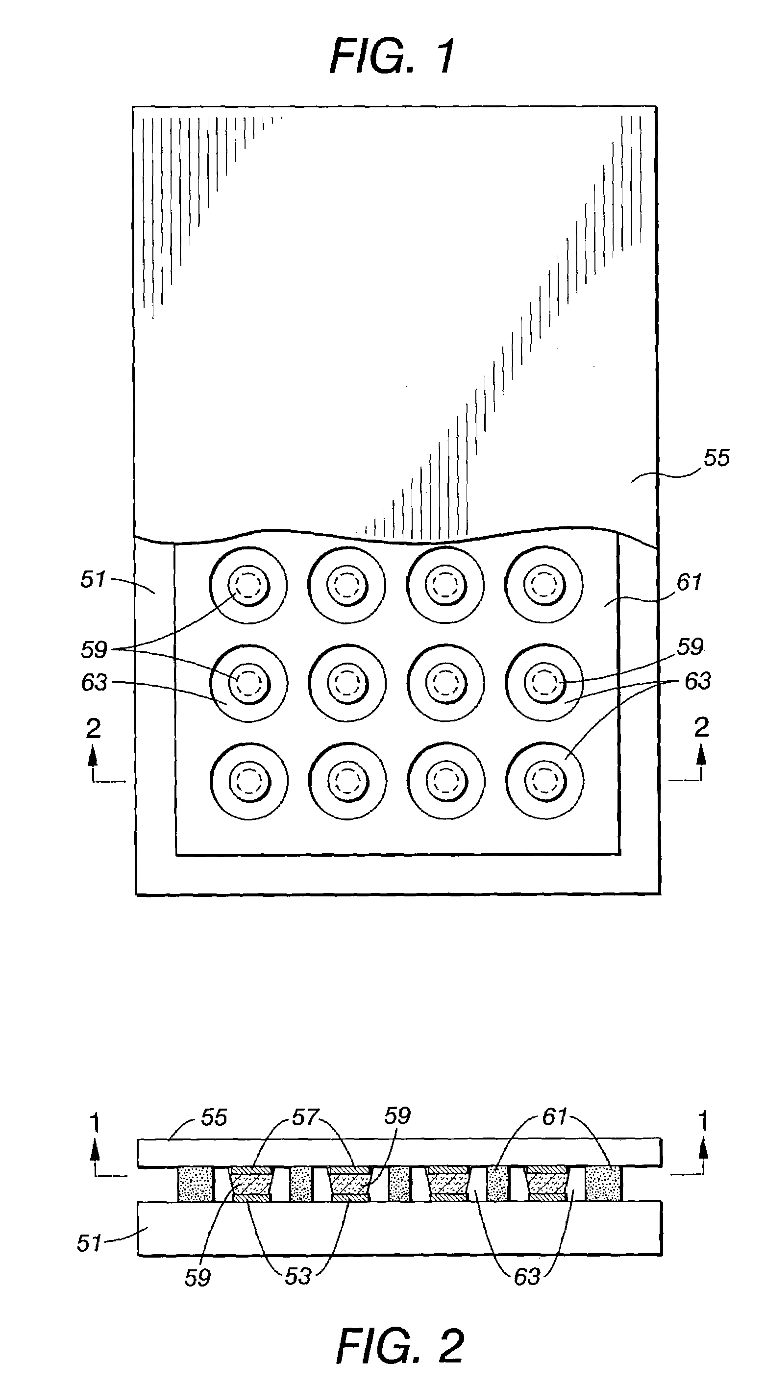
[0006]FIG. 1 and FIG. 2 are a schematic plan view and a schematic elevational cross-sectional view of an embodiment of an interconnected circuit structure that can be made using techniques disclosed herein. The circuit structure includes a first electrical circuit structure 51 that includes a plurality of contact regions 53. The circuit structure further includes a second electrical circuit structure 55 that a plurality of contact regions 57. The contact regions 53 of the first circuit structure 51 are aligned with the contact regions 57 of the second circuit structure 55. The contact regions 53 are electrically interconnected to corresponding contact regions 57 by conductive islands or bumps 59. A patterned standoff structure 61 is disposed between the first circuit structure and the second circuit structure. The standoff structure 61 includes a plurality of apertures 63, each of which surrounds an interconnection of a contact region 53, a conductive bump 59, and a contact region 5...


PUM

PropertyMeasurementUnit
diameteraaaaaaaaaa
diameteraaaaaaaaaa
thicknessaaaaaaaaaa

Abstract

A multi-layer standoff / mask structure including a standoff having a plurality of standoff openings and a mask having a plurality of mask openings aligned with the standoff openings.

Description

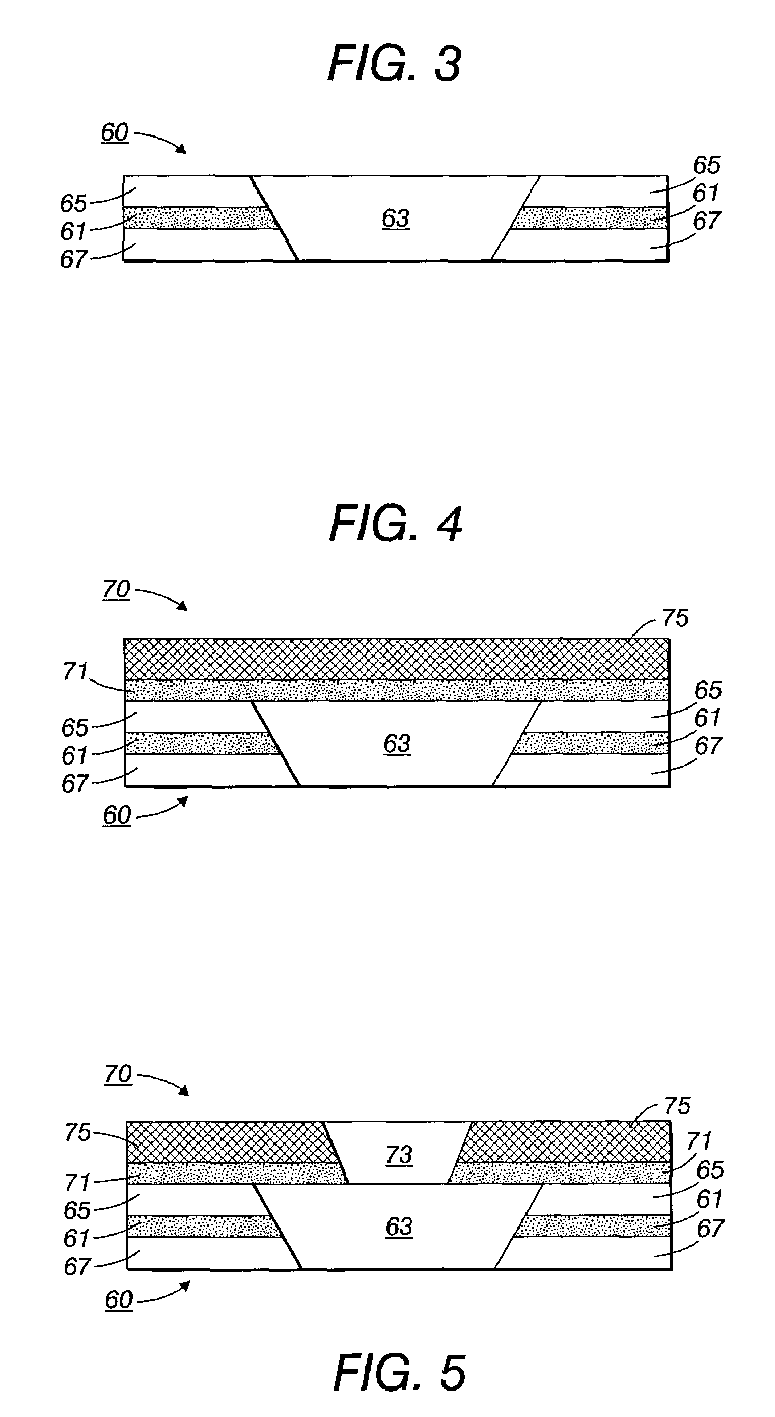
BACKGROUND OF THE DISCLOSURE[0001]The subject disclosure is generally directed to techniques for interconnecting circuit structures.[0002]Circuit structures such as circuit boards, integrated circuit die, and circuit packages are mechanically and / or electrically interconnected by a variety of techniques and it can be difficult to reliably and efficiently mechanically and electrically interconnect circuit structures.BRIEF DESCRIPTION OF DRAWINGS[0003]FIG. 1 is a schematic plan view of an embodiment of an interconnected electrical circuit structure.[0004]FIG. 2 is a schematic elevational view of the interconnected electrical circuit structure of FIG. 1.[0005]FIGS. 3, 4, 5, 6, 7, 8 and 9 are schematic transverse cross-sectional views illustrating various stages in the manufacture of the interconnected circuit structure of FIG. 1.DETAILED DESCRIPTION OF THE DISCLOSURE[0006]FIG. 1 and FIG. 2 are a schematic plan view and a schematic elevational cross-sectional view of an embodiment of an...

Claims


Application Information

Patent Timeline
Patent Type & Authority Patents(United States)
IPC IPC(8): H05K1/02H05K3/32H01L21/60H01L21/68H05K1/14H05K3/12H05K3/30H05K3/34H05K3/36H05K3/46
CPCH01L24/11H01L24/16H01L24/83H01L24/90H05K3/1225H01L24/12Y10T428/24843H01L2224/1147H01L2224/11472H01L2224/11474H01L2224/1148H01L2224/13021H01L2224/13099H01L2224/16225H01L2224/83101H01L2224/83191H01L2224/838H01L2924/01004H01L2924/01015H01L2924/01033H01L2924/01047H01L2924/01049H01L2924/01079H01L2924/14H05K3/305H05K3/321H05K3/3484H05K3/361H05K2201/2036H05K2203/0537H01L2224/2919H01L2924/01005H01L2924/01006H01L2924/014H01L2924/0665Y10T29/49144Y10T29/49126H01L2924/00H01L24/05H01L24/13H01L24/27H01L24/29H01L24/32H01L24/73H01L24/81H01L2224/05568H01L2224/05573H01L2224/06131H01L2224/11005H01L2224/13007H01L2224/13294H01L2224/133H01L2224/13309H01L2224/16013H01L2224/16058H01L2224/16145H01L2224/16227H01L2224/27003H01L2224/2711H01L2224/27438H01L2224/29006H01L2224/29011H01L2224/29191H01L2224/2929H01L2224/29339H01L2224/32013H01L2224/32145H01L2224/32225H01L2224/73103H01L2224/73203H01L2224/81191H01L2224/81801H01L2224/8185H01L2224/81903H01L2224/8385H01L2224/83862H01L2924/12042H05K3/3485H01L2924/00012H01L2924/00014H01L2924/0635H01L2924/066H01L2924/07025
Inventor ANDREWS, JOHN R.GERNER, BRADLEY J.SCHMACHTENBERG, III, RICHARDSLENES, CHADSCHULTZ, SAMUEL V.
Owner XEROX CORP
Learn More