Push-button switch units for vehicle interior light assembly

a technology of push-button switch and vehicle interior light assembly, which is applied in the direction of contact, contact mechanism, transportation and packaging, etc., can solve the problems of deteriorating product value and inability to smooth switch operation, and achieve the effect of preventing product value from deteriorating and preventing tilting

Active Publication Date: 2006-02-14
T & T
View PDF11 Cites 26 Cited by
  • Summary
  • Abstract
  • Description
  • Claims
  • Application Information

AI Technical Summary

Benefits of technology

[0006]In view of these circumstances described above, an object of the present invention is to provide a push-button switch unit in which a push button is adapted to move while maintaining an aligned state regardless of the location at which the push button is pressed. A further object of the present invention is to provide a push button having minimal if any) injection molding sink marks such that the product value is maintained.
[0008]A side surface of each prismatic segment which is disposed the farthest distance from the columnar segment is preferably flat so as to provide an increased surface area, whereby the push button is prevented from tilting even when the push button is pressed in a lopsided or off-center manner.
[0010]As described above, according to the present invention, the pair of shaft rods each having the columnar segment and the prismatic segment may be provided on the undersurface of the push button, while the shaft sockets having the circular hole segment and the rectangular hole segment for receiving the correspondingly configured shaft rod may be provided in the main body. Alternatively, the pair of shaft rods each having the columnar segment and the prismatic segment may be provided on the main body, while the shaft sockets each having the circular hole segment and the rectangular hole segment for receiving the corresponding shaft rod may be provided in the push button. Consequently, even when the push button is pressed in a lopsided or off-center manner, the push button moves while maintaining a longitudinally aligned state and thus is not tilted or skewed in the longitudinal direction. Moreover, because each of the shaft rods is provided with a large cross-sectional surface area, sink marks are prevented from being formed when such parts are injection molded. Accordingly, this prevents the product value from deteriorating.
[0011]Since the flat side surface of each prismatic segment provides a large surface area, the push button is further prevented from tilting when the push button is pressed in a lopsided manner.

Problems solved by technology

In such a case, a smooth switch operation cannot be performed.
This is problematic in that the product value is deteriorated.

Method used


Image

  • Push-button switch units for vehicle interior light assembly
  • Push-button switch units for vehicle interior light assembly
  • Push-button switch units for vehicle interior light assembly

Examples


Embodiment Construction

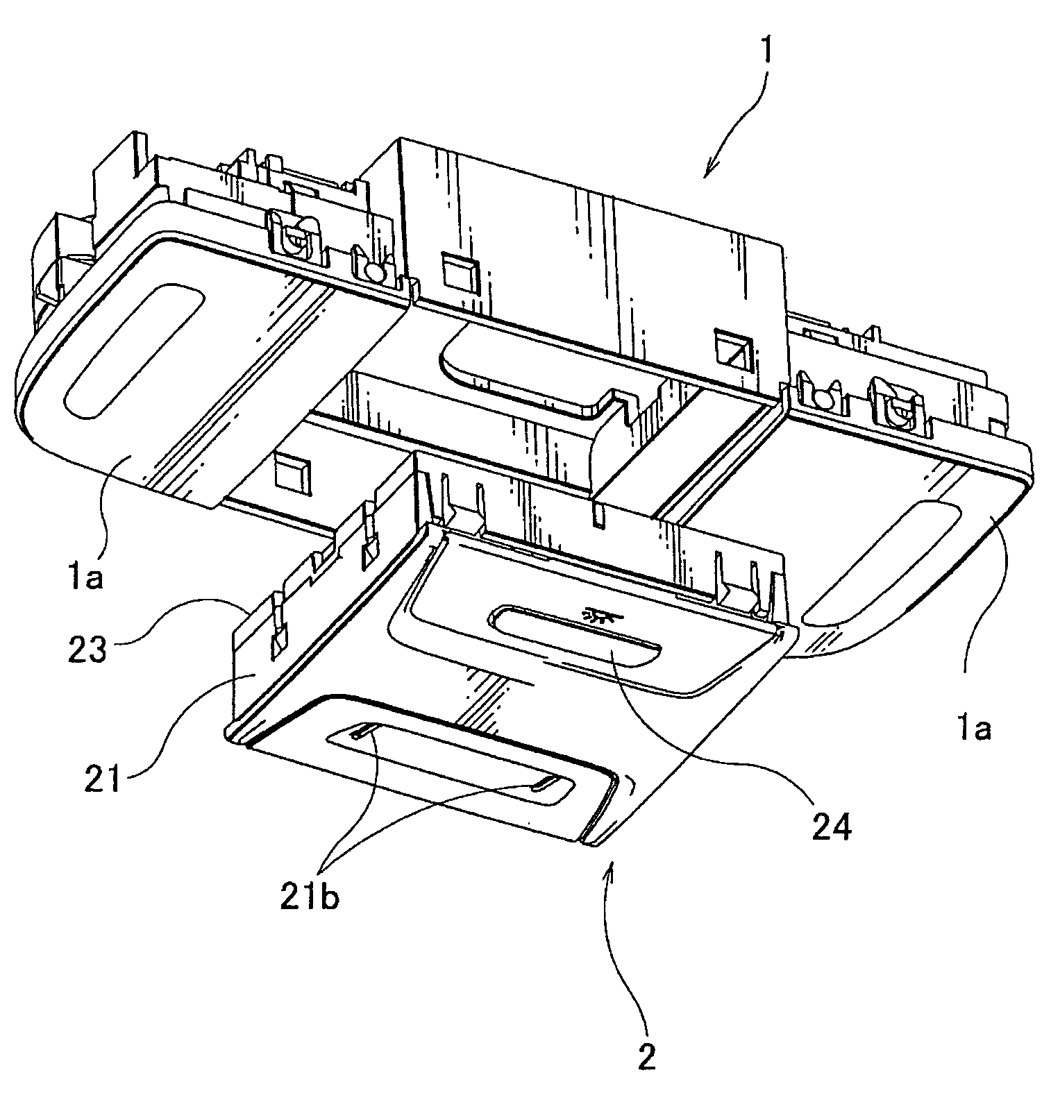
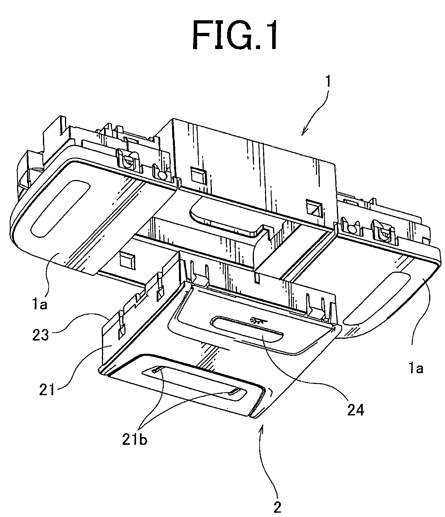
[0021]Embodiments of a push-button switch unit according to the present invention will be described with reference to the accompanying drawing FIGS. 1–7. In this regard, Either an undersurface of the push button or the main body is provided with a pair of shaft rods each having a columnar cylindrical segment and a prismatic segment. On the other hand, the other of the push button or the main body includes shaft sockets each having a circular hole segment and a rectangular hole segment for receiving a shaft rod of corresponding geometry. The push-button switch unit according to the present invention is used in, for example, an in-vehicle interior light device.

[0022]FIG. 1 is a perspective view of the in-vehicle interior light device having a box-like main body 1 formed by, for example, injection molding. The main body 1 has three chambers which are separated from one another with respect to the longitudinal direction. The left and right chambers each accommodate a lamp and a push swi...


PUM


Abstract

A push-button switch unit includes a push switch which is fixed to a main body and includes an operating part; and a push button fitted to the operating part. The push button is pressed in order to turn the push switch on and off. An undersurface of the push button is provided with a pair of shaft rods each having a columnar segment and a prismatic segment. The main body includes shaft sockets each having a circular hole segment and a rectangular hole segment for receiving a corresponding one of the shaft rods.

Description

BACKGROUND OF THE INVENTION[0001]1. Field of the Invention[0002]The present invention relates to push-button switch units for turning on and off a lamp disposed in an in-vehicle interior light assembly. More particularly, the present invention relates to push button structures attached to an operating part of a push switch.[0003]2. Description of the Related Art[0004]Japanese Unexamined Utility Model Registration Application Publication No. 63-45923, for example, discloses a conventional push-button switch unit in which a push button is attached to an operating part of a push switch. According to such a push-button switch unit, the operating part of the push switch is fixed to a casing, and the push button is provided with cylindrical guiding columns. The cylindrical guiding columns engage with circular guiding holes provided in an operating surface of the casing. When the push button is pressed, the operating part of the push switch is pressed such that the push switch is turned on...

Claims


Application Information

Patent Timeline
Patent Type & Authority Patents(United States)
IPC IPC(8): H01H3/12B60Q3/02H01H1/58H01H13/14
CPCB60Q3/0296H01H13/14H01H1/5805H01H2221/026H01H2219/04B60Q3/82H01H13/50
Inventor SHIMODA, YUJIOCHIAI, HIROSHI
Owner T & T
Why Eureka
Try Eureka