
Modular electrical distribution system

Active Publication Date: 2006-02-14
HILL PHOENIX
View PDF5 Cites 35 Cited by
  • Summary
  • Abstract
  • Description
  • Claims
  • Application Information

AI Technical Summary

Problems solved by technology

Further, a custom-built onsite installation may inefficiently utilize space as the components provided by the various manufacturers may not permit vertical stacking, and may not be efficiently integrated with one another.

Method used


Image

  • Modular electrical distribution system
  • Modular electrical distribution system
  • Modular electrical distribution system

Examples


Embodiment Construction

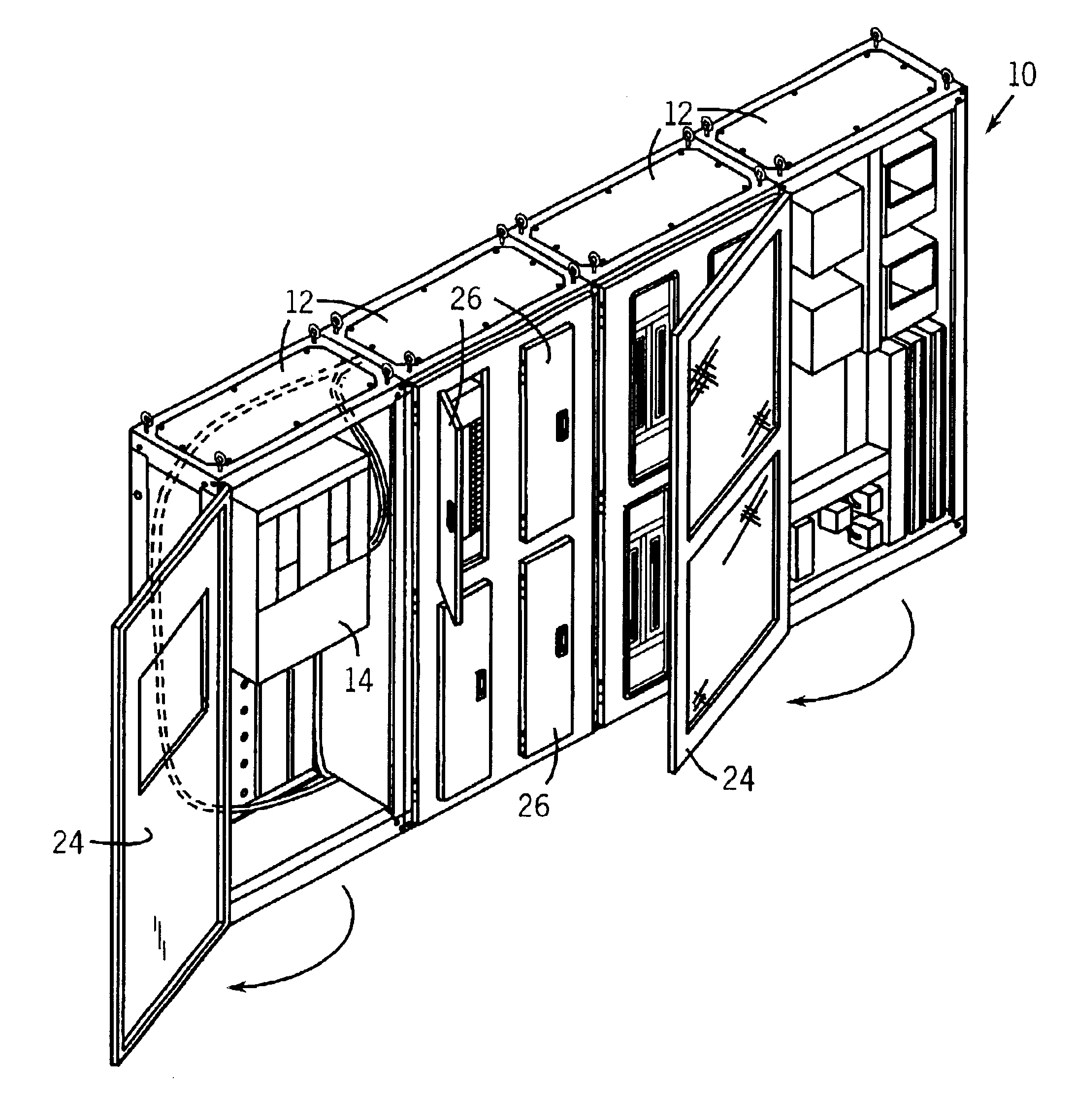
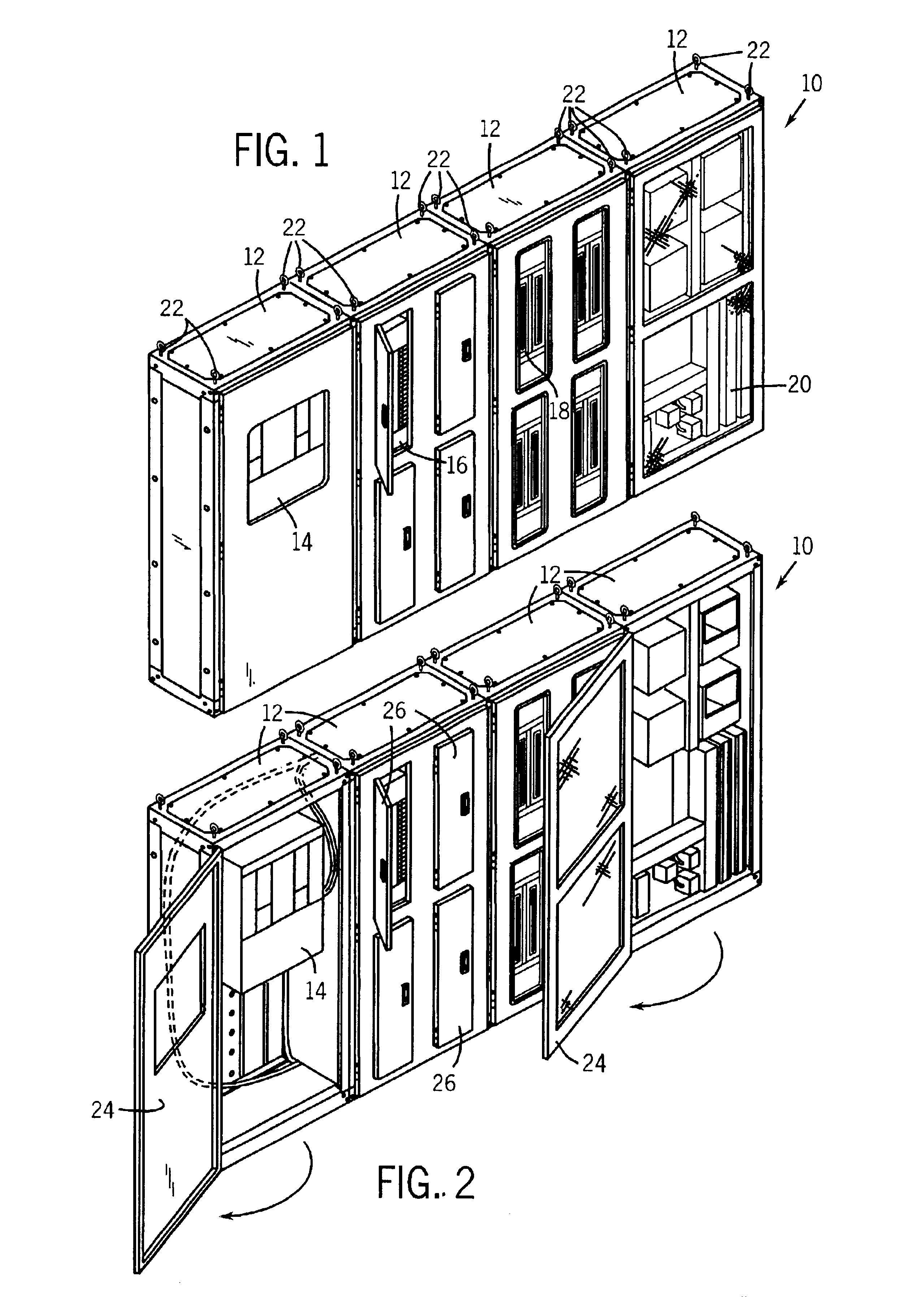
[0024]Referring to FIG. 1, an electrical distribution center 10 is constructed of a number of linked modules, shown as segments 12. As depicted in FIG. 1, electrical distribution center 10 includes four linked segments 12 but may include more or less segments 12 depending on the desired configuration of electrical distribution center 10.

[0025]Each segment 12 serves as a modular component of electrical distribution center 10. Each segment 12 may house an electrical component or components desired for use in electrical distribution center 10. For example, as depicted in FIG. 1, various segments 12 may include one or more of a main distribution panel 14, panelboards 16, contactor boards 18, and a variety of techboards 20. The electrical components depicted in the electrical distribution center 10 of FIG. 1 are intended for illustrative purposes only, and are not meant to be limiting. Additional types of electrical components may include lighting control systems, alarm control systems, ...


PUM


Abstract

A modular electrical distribution system includes a number of linked segments. A first electrical component is mounted in one of the segments and a second electrical component is mounted in another one of the segments. The first and second electrical components are made by different manufacturers. The linked segments are configured to be transported as a single unit without an additional external framework.

Description

FIELD OF THE INVENTION[0001]The present invention relates to an electrical distribution system. In particular, the present invention relates to a modular power distribution unit configured to house multiple types of electrical equipment.BACKGROUND OF THE INVENTION[0002]Facilities, such as commercial buildings or office complexes, typically have one or more centralized electrical distribution centers that include the electrical components required to operate the facility. Such electrical components may include a main distribution panel, panelboards, lighting control centers, transformers, telephone systems, computer systems, and so forth.[0003]When a facility is being constructed or remodeled, a new electrical distribution center may be desired. One way of constructing an electrical distribution center is to order the various electrical components from the associated manufacturers or distributors and individually mount the components onto a framework built and wired at the facility i...

Claims


Application Information

Patent Timeline
IPC IPC(8): H02B1/00
CPCH02B1/01
Inventor CALCOTE, GRADY L.
Owner HILL PHOENIX
Learn More