Backwash flushing filter

a filter and backwash technology, applied in the direction of moving filter element filters, filtration separation, separation processes, etc., can solve the problems of increasing the time the filter system is offline and out of operation, further reducing the efficiency of the filtration system,

Active Publication Date: 2006-02-21
THE SOURCE RCO PARTS INC
View PDF6 Cites 30 Cited by
  • Summary
  • Abstract
  • Description
  • Claims
  • Application Information

AI Technical Summary

Problems solved by technology

Likewise, the solids retained on the filter may slough due to gravitational force and begin to form a sediment which collects at the lower end of the filter assembly which further decreases the efficiency of the filtration system.
As such, the lower filter assembly usually requires manual cleaning by the operator, which increases the time the filter system is offline and out of operation.
Unfortunately, most filtration backwash systems require the filter to be taken offline and placed out of service while the backwash operation is performed.
This is due, in part, to the consistent design of filtration systems wherein the filter assembly does not provide an efficient mechanism for removing sedimentary solids which have accumulated at the bottom of the filter assembly.

Method used


Image

  • Backwash flushing filter
  • Backwash flushing filter
  • Backwash flushing filter

Examples


Embodiment Construction

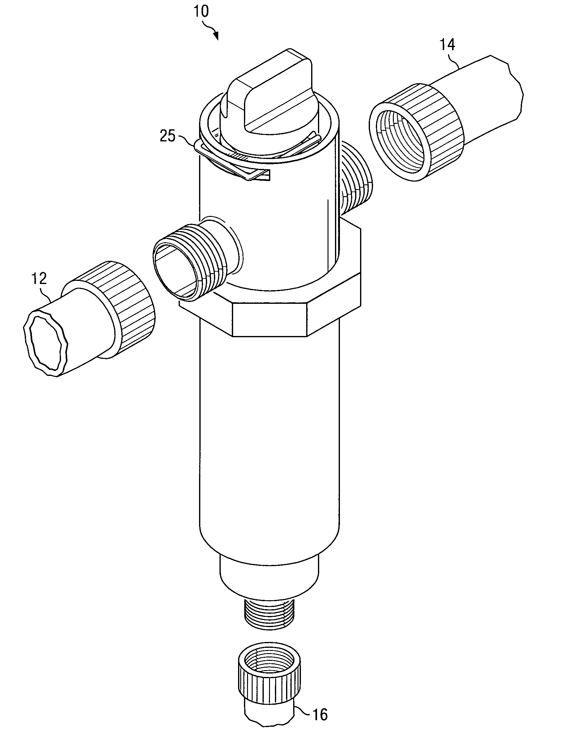
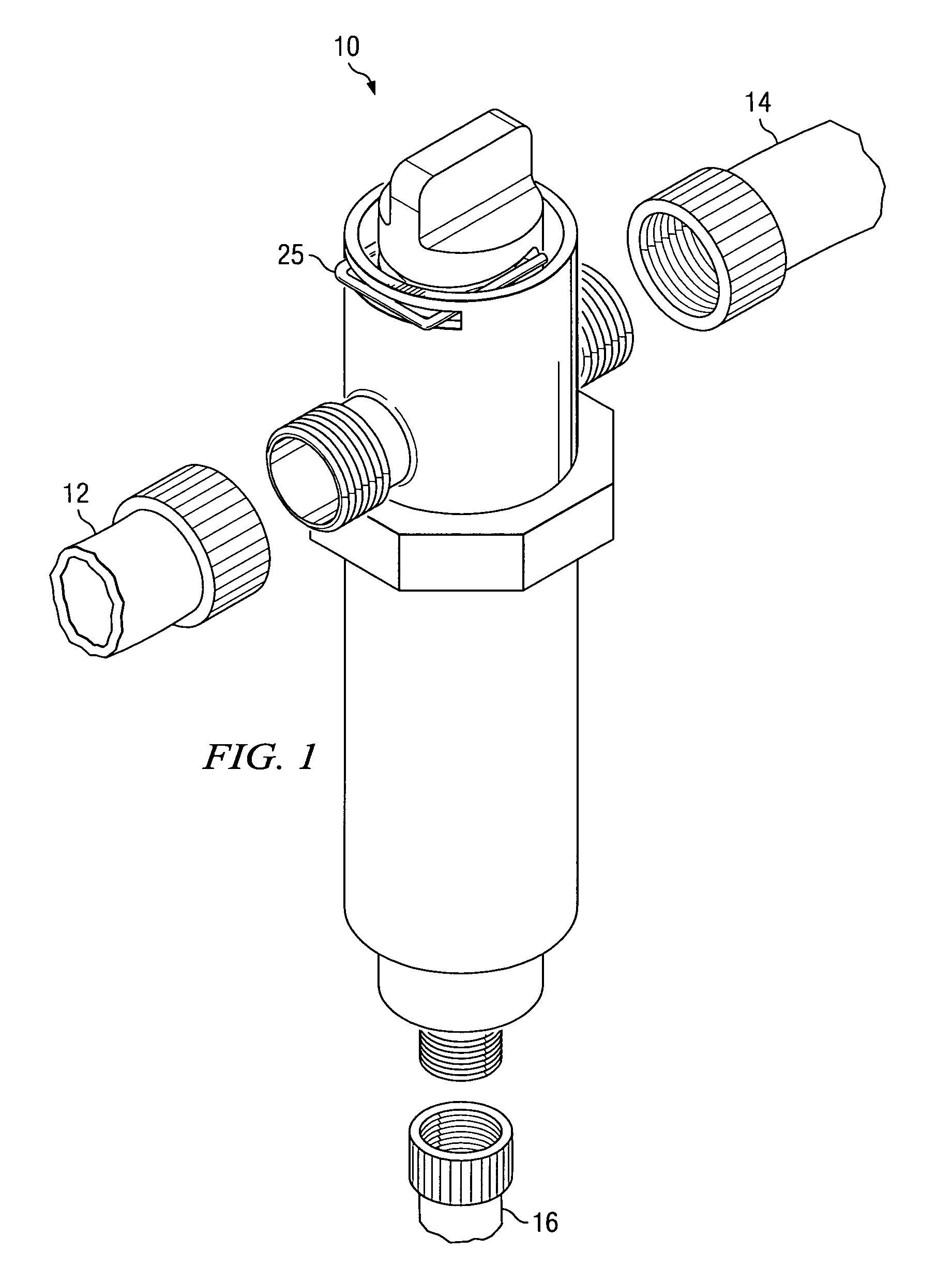
[0020]The preferred embodiment of the invention disclosed herein as shown in FIGS. 1-4D is a backwash flushing filter assembly 10 whereby switching from filtration mode to backwash flushing mode is performed by a one-quarter turn of the rotatable valve assembly and vice versa as discussed in further detail below.

[0021]FIG. 1 depicts the assembled backwash flushing filter assembly 10 with connection points to a fluid source pipe 12, filtered fluid outlet pipe 14, and backwash drain pipe 16. The filter assembly 10 is preferably constructed so that the filter assembly 10 can be readily accessed to permit visual component inspection, filter media removal and replacement, if necessary. The filter assembly 10 can be constructed in a variety of sizes to accommodate both standard and custom filter element sizes and uses as known in the art.

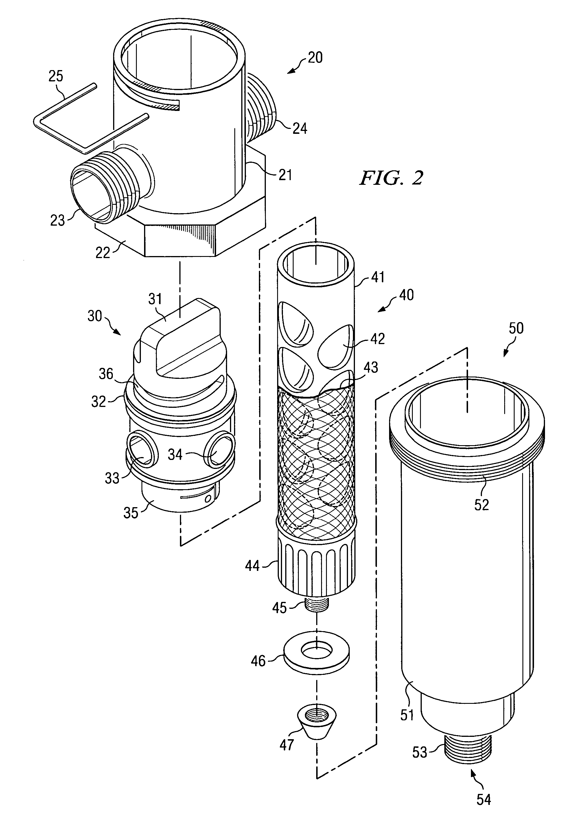
[0022]Turning now to FIG. 2, the backwash flushing filter assembly 10 is shown in exploded view. Filter assembly 10 is comprised of a header assembly 20,...


PUM

PropertyMeasurementUnit
circumferenceaaaaaaaaaa
circular shapeaaaaaaaaaa
rotationaaaaaaaaaa

Abstract

An inline backwash, flushing filter assembly comprising a header assembly, a rotatable valve assembly, and a filter element assembly disposed within a filter housing assembly. In operation, the controller moves the turn knob of the rotatable valve assembly a one-quarter turn which results in the reversal of fluid flow through the assembly to periodically back flush the filter utilizing fluid from the system inlet. Debris removed from the filter element during the backwash process are immediately discharged from the system through a drain port. Simultaneously, the hydraulic shearing mechanism of the backwash process dislodges and drains debris which may have accumulated on the screen and at the bottom of the lower filter assembly during normal filter operations. The controller then returns the filter assembly to filtration operation by a reverse one-quarter turn of the turn knob of the rotatable valve assembly.

Description

BACKGROUND OF THE INVENTION[0001]1. Technical Field[0002]The present invention relates to an apparatus and method for improving the cleaning operation of an inline filter and, more specifically, for the backwash and flushing of the filter element and filter assembly without taking the filter assembly offline for a prolonged period and does not require any special tools or skills to operate.[0003]2. Description of Related Art[0004]Filters are commonly used to remove particulates and undesired solids from a fluid medium. A common filtration process involves passing a fluid through a filter medium. Solids are retained on the filter medium, while the fluid passes through the filter medium and continues down stream. However, as solids begin to accumulate on the filter media, the differential pressure across the filter medium increases and consequentially the fluid flow rate decreases. Likewise, the solids retained on the filter may slough due to gravitational force and begin to form a se...

Claims


Application Information

Patent Timeline
Patent Type & Authority Patents(United States)
IPC IPC(8): B01D21/24B01D24/38B01D29/88B01D33/70B01D35/00B01D29/15
CPCB01D29/15B01D29/668B01D2201/0415
Inventor WALTON, FRANK A.MANN, JAMES A.WILLIAMS, JAMES E.
Owner THE SOURCE RCO PARTS INC
Why Eureka
Try Eureka