
Fibrous filtration face mask

a technology of fibrosis and face mask, applied in the direction of filtration separation, separation process, application, etc., can solve the problems of generating excess quantities of fiber waste, causing fiber to fall into the open area, and causing fiber to be loosened, so as to improve the effect of surface fuzz, and reduce the creation of surface fuzz

Inactive Publication Date: 2006-11-07
3M CO
View PDF31 Cites 194 Cited by
  • Summary
  • Abstract
  • Description
  • Claims
  • Application Information

AI Technical Summary

Benefits of technology

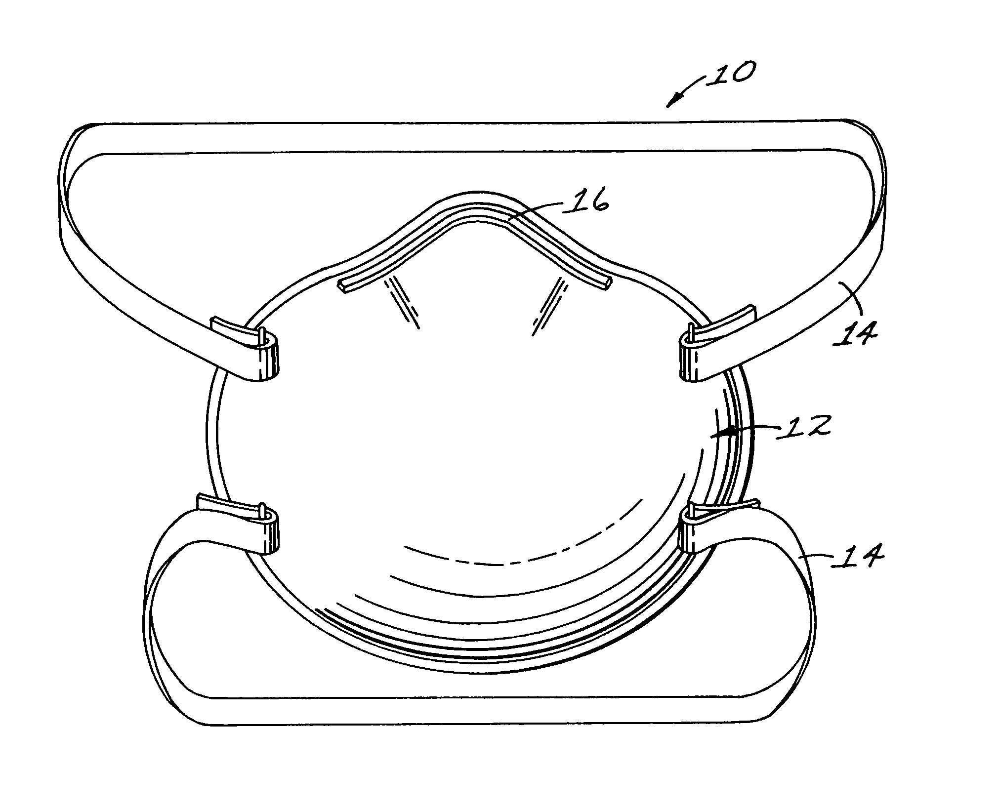
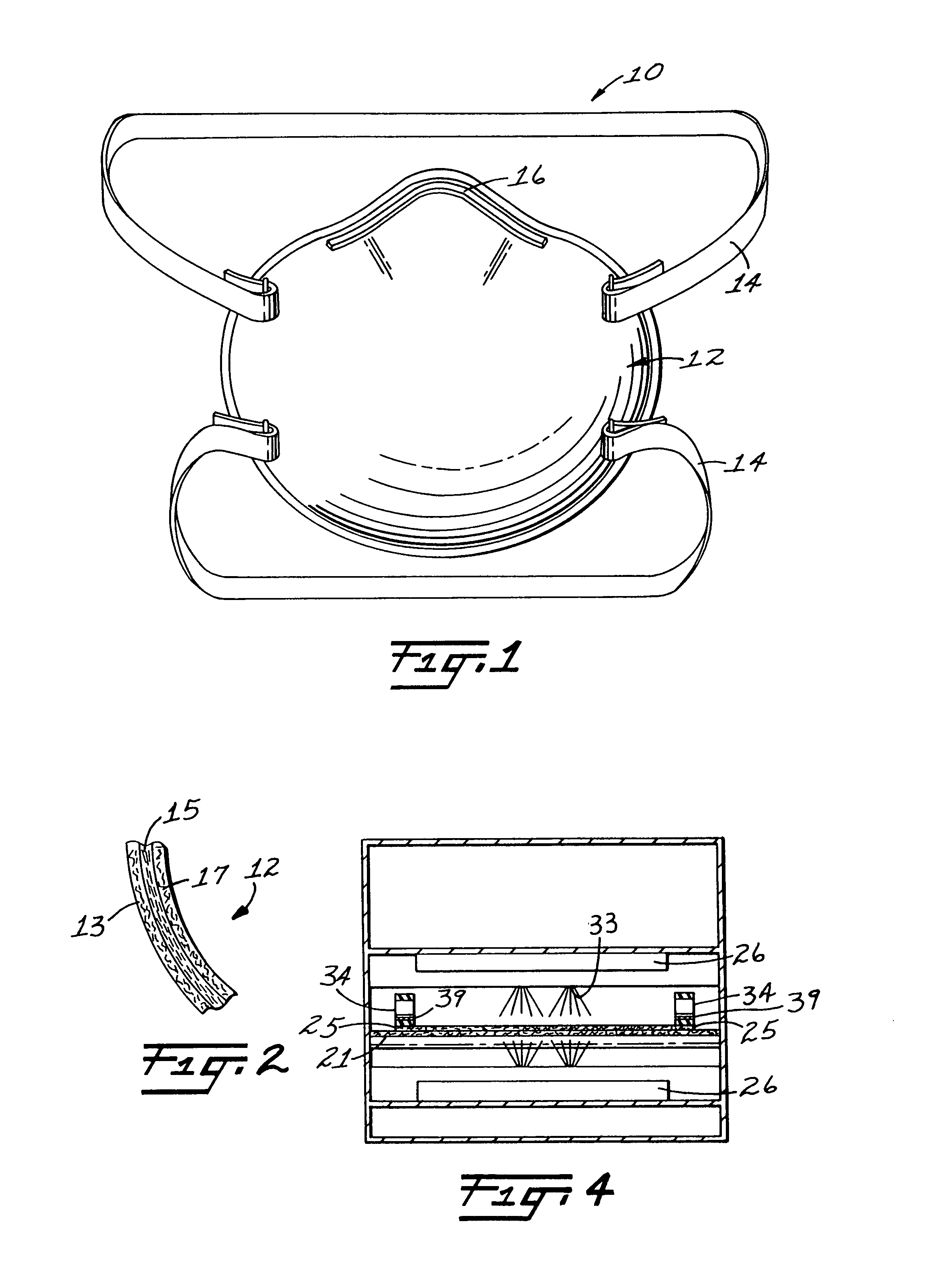
[0016]There are two important reasons for providing face masks that have improved surface fuzz properties. The first reason was indicated above: the fuzz is an irritant to the face of the wearer. The second reason (not any less important than the first) is that the fuzz can come loose from the mask and can be inhaled through the nostrils of the wearer or may get into the wearer's mouth. In addition, loose fuzz is particularly dangerous to a patient having an open wound, cut, or incision. If a physician is treating such a patient and is wearing a face mask to protect the patient from infection, and the mask has a high degree of surface fuzz, there is a greater risk that a fiber could become dislodged from the mask and fall into the open area. Accordingly, a primary object of this invention is to substantially reduce the creation of surface fuzz on a shaping layer of a face mask made from a non-woven web of thermally bonding fibers.
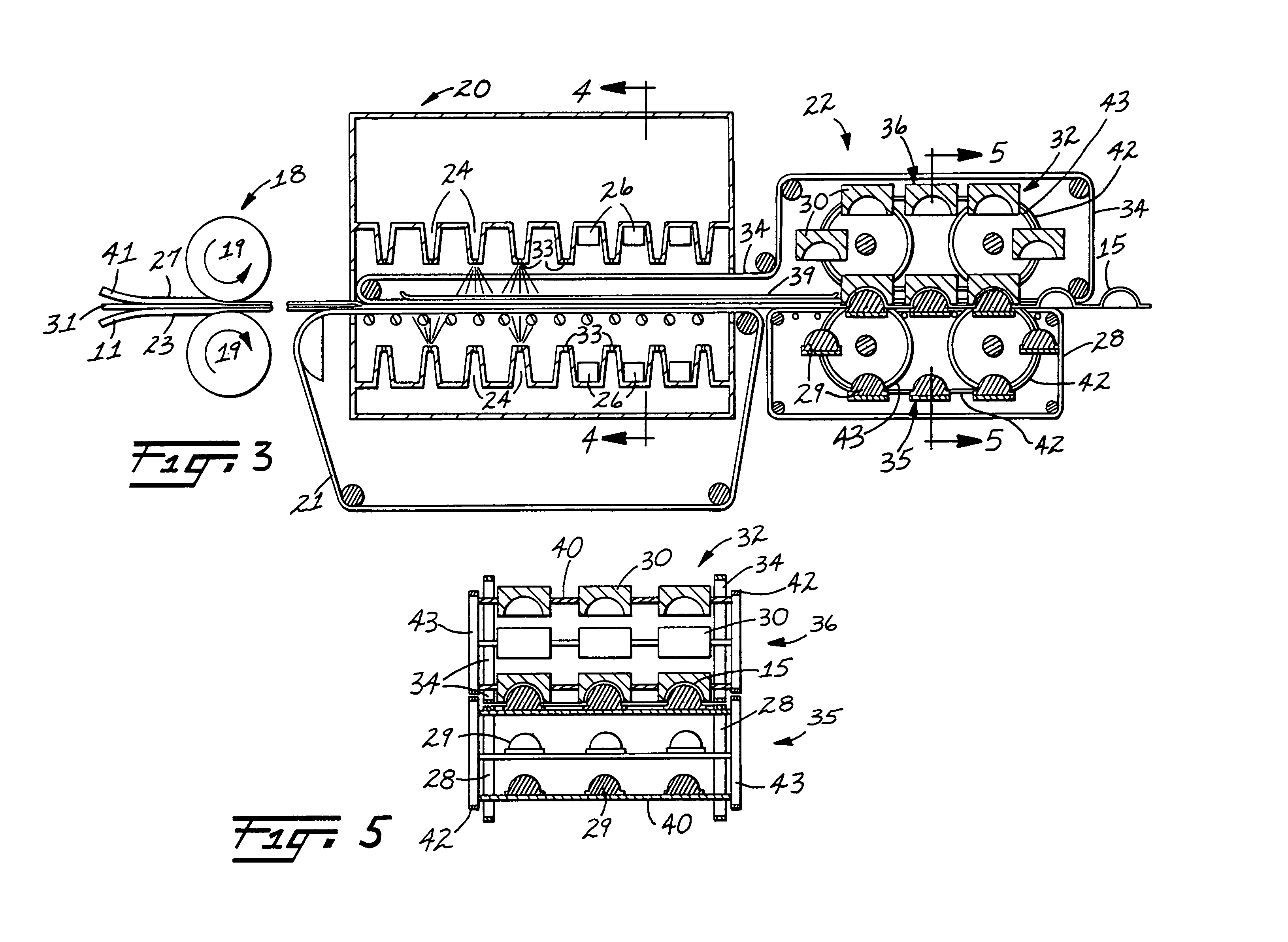
[0017]In addition to providing a face mask having improved surface fuzz properties, this invention provides new methods for forming face masks which possess superior operating characteristics over the prior art methods of hot molding non-woven webs of thermally bonding fibers. In known hot molding methods of forming fibrous filtration face masks, there is a tendency for fibers in the non-woven web to stick to the hot molds. When fiber sticking occurs, the molded shells deform upon opening of the molds. The shells will be permanently deformed upon cooling. The hot molding process therefore tends to generate excess quantities of fiber waste. Although sticking may be avoided in hot molding by carefully controlling the process parameters, the process window (variation in process conditions) is relatively narrow and becomes extremely difficult to control in a continuous process. Accordingly, another object of this invention is to provide a method of forming a shaping layer from a non-woven web of thermally bonding fibers, which method avoids fibers sticking to the molds.

Problems solved by technology

In addition, loose fuzz is particularly dangerous to a patient having an open wound, cut, or incision.
If a physician is treating such a patient and is wearing a face mask to protect the patient from infection, and the mask has a high degree of surface fuzz, there is a greater risk that a fiber could become dislodged from the mask and fall into the open area.
The hot molding process therefore tends to generate excess quantities of fiber waste.
Although sticking may be avoided in hot molding by carefully controlling the process parameters, the process window (variation in process conditions) is relatively narrow and becomes extremely difficult to control in a continuous process.

Method used


Image

  • Fibrous filtration face mask
  • Fibrous filtration face mask
  • Fibrous filtration face mask

Examples


examples

[0052]In the following examples, cup-shaped shaping layers were formed using cold and hot molding techniques and various fiber blends. The shaping layers were tested for surface fuzz after being subjected to abrasion, and the results of those tests are tabulated in Table 1. In FIG. 5, a comparison of surface fuzz values for cold and hot molded fibrous shells is illustrated. The data plotted in FIG. 5 is for shells consisting of bicomponent and binder fibers. Line 37 indicates surface fuzz values for hot molded shells, and line 38 indicates surface fuzz values for cold molded shells.

examples 1 – 20

Examples 1–20

[0053]In these examples, non-woven fibrous webs were cold molded. The molded non-woven webs contained bicomponent fibers that had a PET core surrounded by a sheath of a copolyester blend. In some of the examples, the fibrous web was preskinned. In other examples, there was no preskinning step. Examples 1–20 demonstrate that surface fuzz creation is reduced with preskinning and increasing bicomponent fiber content. The examples also demonstrate that surface fuzz creation is further reduced with increasing preskinning temperatures. In all of these examples, the molded fibers did not stick to the molds.

example 1 (

No Preskinning)

[0054]A non-woven fibrous web composed of 100 percent bicomponent MELTY Type 4080 fibers formed in a RANDO WEBBER air-laying machine was molded into shaping layers. The web was heated to a temperature of approximately 190° C. by simultaneously applying hot air and infra-red heat to the web. Hot air impinged upon the top of the web and IR heat was applied to the top and bottom of the web. After heating, the hot web was molded by placing it between cup-shaped unheated male and female molds. Four shells were randomly selected and were then tested for surface fuzz. These shells had a calculated average fuzz value of 9.5

Surface Fuzz Abrasion Test

[0055]The fuzz values were determined as follows:

[0056]Each molded shell was placed on a cup-shaped mandrel and was subjected to abrasion by dragging a stiff, flat brush over a surface of the face mask from the base of one side to the base of an opposing side. A total force of approximately 1.3 Newtons was exerted by the brush on e...


PUM

PropertyMeasurementUnit
Fractionaaaaaaaaaa
Percent by massaaaaaaaaaa

Abstract

A face mask for filtering contaminants from the air. The face mask includes a harness for securing the mask over the nose and mouth of the wearer and a nonwoven fibrous layer attached to the harness. The nonwoven fibrous layer contains at least 40 weight percent thermally bonding fibers, where at least 10 weight percent of the fibers in the nonwoven fibrous layer are bicomponent fibers. The nonwoven fibrous layer is molded in a cup-shaped configuration and has a surface fuzz value of not less than 7.5 after being subjected to a surface fuzz abrasion test.

Description

[0001]This is a continuation of application Ser. No. 08 / 154,989 filed Nov. 18, 1993 now abandoned, which is a division of application Ser. No. 07 / 632,964 filed Dec. 20, 1990 now U.S. Pat. No. 5,307,796 now abandoned.FIELD OF THE INVENTION[0002]This invention pertains to methods of forming fibrous-filtration-face-masks from non-woven webs of thermally bonding fibers. The invention also pertains to fibrous-filtration-face-masks made from non-woven webs of thermally bonding fibers, which masks maintain low degrees of surface fuzz after being subjected to abrasion.BACKGROUND OF THE INVENTION[0003]Fibrous-filtration-face-masks are well known in the respiratory art. Such face masks are worn over the breathing passages of a person and typically serve at least one of two purposes: (1) to prevent impurities or contaminants from entering the wearer's breathing tract; and (2) to protect others from being exposed to bacteria and other contaminants exhaled by the wearer. In the first situation, ...

Claims


Application Information

Patent Timeline
IPC IPC(8): A62B7/10A41D13/11A61B19/00B01D39/08B01D39/16D04H1/54
CPCA41D13/1146A62B23/025B01D39/1623B01D2239/0216B01D2239/065B01D2239/0681B01D2239/086B01D2239/10D04H1/54D04H1/541D04H1/544D04H1/55
Inventor KRONZER, JOSEPH P.DYRUD, JAMES F.
Owner 3M CO
Learn More