Mixed fuel coal burner for gas turbines

a gas turbine and mixed fuel technology, applied in the direction of engines, machines/engines, mechanical equipment, etc., can solve the problems of slow coal burn rate, inability to control the primary air flow rate, and slow radiation heat transfer rate, so as to reduce the creation of undesirable soot or tar

Inactive Publication Date: 2007-04-12
FIREY JOSEPH CARL
View PDF4 Cites 22 Cited by
  • Summary
  • Abstract
  • Description
  • Claims
  • Application Information

AI Technical Summary

Benefits of technology

[0027] In a mixed fuel coal burner of this invention, coal chunks pass through two separate reaction chambers in series. In the first, ODD, reactor chamber the coal is heated by a throughflow of hot gas, containing some molecular oxygen, in order to carry out oxidative destructive distillation, ODD, of the coal volatile matter. The molecular oxygen content of these hot gases is less than stoichiometric, relative to the coal volatile matter, so that partial oxidation of only the volatile matter occurs in the ODD reactor chamber. Two fuel products thus emerge from the ODD reactor chamber; a devolatilized coke product, which is passed into the second coke reaction chamber; and a partially oxidized coal volatile matter gas. The partially oxidized coal volatile matter gas is mixed with an overfire air, and fully burned, in an ODD overfire burner chamber, and the resulting burned gases pass into the turbine. Partially oxidized volatile matter can thus be burned cleanly in the ODD overfire burner chamber, with greatly reduced creation of undesirable soot or tar, and this is one of the beneficial objects of this invention.
[0031] This is another beneficial object of this invention, over the prior art, that high volatile matter bituminous coals can be burned cleanly, at a high burn rate, and that this burn rate can be controlled, over a wide range, by control of the rate of flow of primary air into the second coke reaction chamber.
[0033] It has been this carryover of ash particles, into the gas turbine engine, and resulting turbine blade damage, which has previously prevented the use of low cost, and readily available, coal fuels in gas turbine engines. At present, gas turbine engines, such as are widely used in combined cycle electric power generating plants, operate only on expensive natural gas, or petroleum distillate fuels. This is a principal beneficial object of this invention, that low cost, ash containing, coals can be cleanly burned, in a gas turbine engine, without ash carryover into the turbine blades.

Problems solved by technology

This radiation heat transfer rate, and hence the coal burn rate, is not only slow, but cannot be controlled by control of the primary air flow rate, as is needed for control of the power output of a gas turbine engine.

Method used


Image

  • Mixed fuel coal burner for gas turbines
  • Mixed fuel coal burner for gas turbines
  • Mixed fuel coal burner for gas turbines

Examples


Embodiment Construction

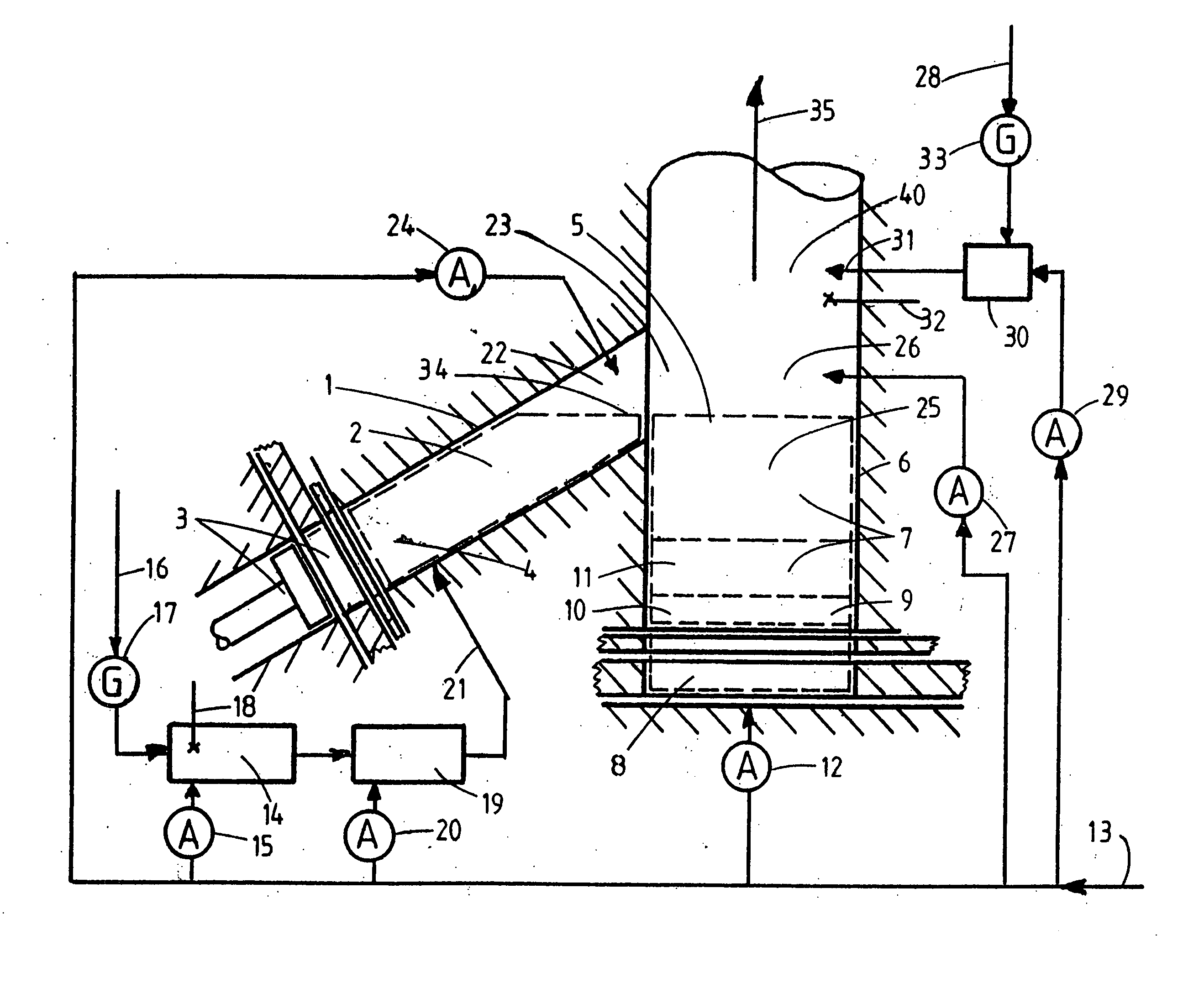
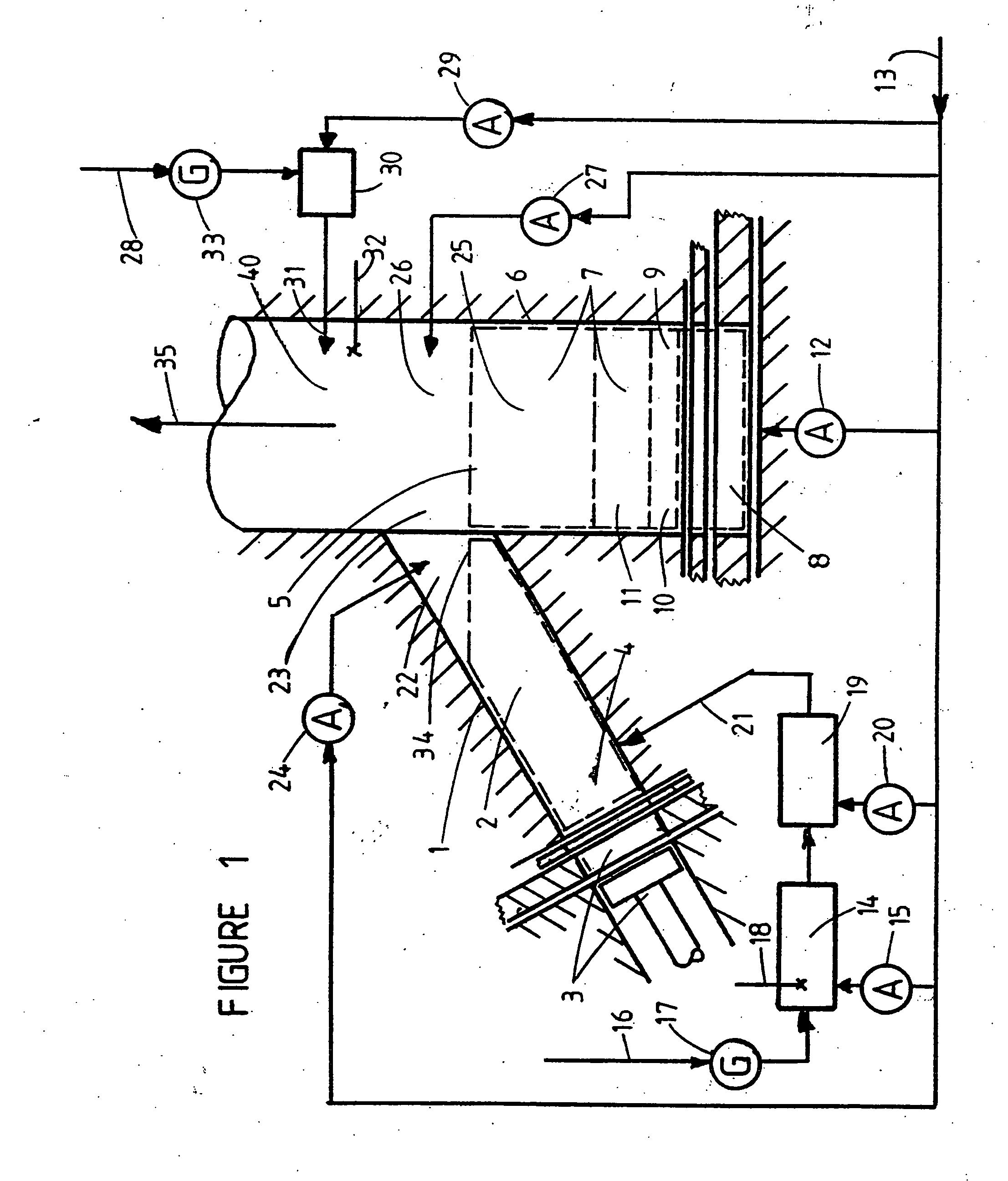
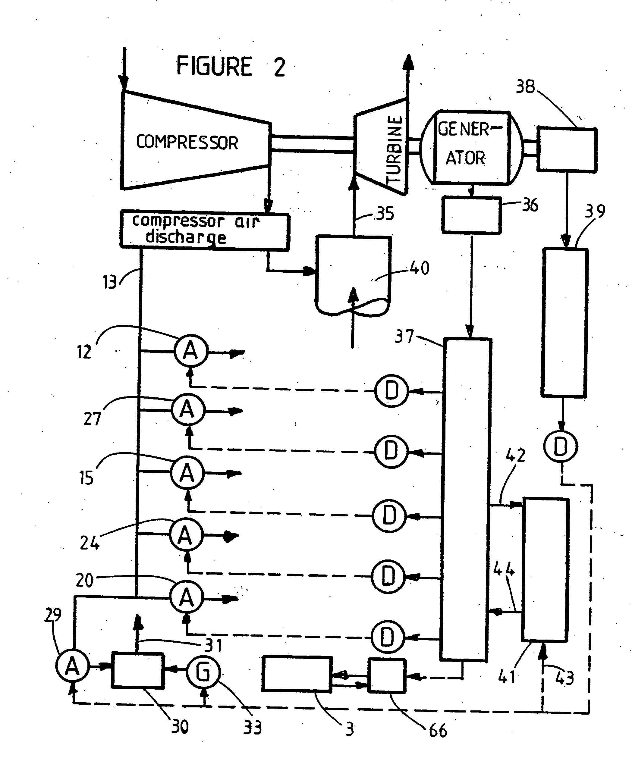
[0049] One example form of a mixed fuel coal burner of this invention is shown schematically in FIG. 1, as adapted for use with a gas turbine engine, and comprises the following elements: [0050] 1. The oxidative, destructive distillation, ODD, reactor comprises an ODD reactor chamber, 2, and enclosure, 1, and a refuel mechanism and driver, 3. The refuel mechanism can transfer coal chunks, periodically, from an external coal supply source, at atmospheric pressure, not shown, sealably into the pressurized lower refuel end, 4, of the ODD reactor chamber, 2. The refuel mechanism, 3, functions thusly to keep the ODD reactor chamber, 2, essentially full of coal undergoing oxidative destructive distillation. Excess coal, reacted to coke, spills out of the upper gas outlet end of the ODD reactor chamber, 2, at each refueling, into the upper end, 5, of the coke reaction chamber, 7, which utilizes overfeed coke fuel delivery. [0051] 2. A portion of the gas turbine engine compressor discharge ...


PUM


Abstract

As shown schematically in FIG. 1, hot gases, containing molecular oxygen, from generator elements, (14) and (19), pass through a bed of coal chunks in an ODD reactor chamber (2). The molecular oxygen content of these hot gases is less than stoichiometric, relative to the coal volatile matter content, so that partial oxidation of only the volatile matter occurs within the ODD reactor chamber, (2), during devolatilization therein. Two products are thusly created, a partially oxidized, and hence cleaner burning, volatile matter fuel gas, and a solid devolatilized coke. The hot coke is transferred, by overfeed, into a coke reaction chamber, (7), where counterflowing primary air, via air meter, (12), gasifies the coke into carbon monoxide with some carbon dioxide. Finally, the carbon monoxide and the partially oxidized volatile matter, are admixed with overfire air, and burned fully to carbon dioxide in overfire burner chambers, (23), (26). The resulting hot burned gases flow into the nozzle inlet, where, after mixing with bypass air, they expand through the expander portion of a gas turbine engine. Coal ashes accumulate at the bottom, (9), of the coke reaction chamber, (7), where the overlying coke chunks prevent ash particle carryover into the turbine blades. Low cost coal can thus be cleanly used as an energy source for gas turbine engines.

Description

CROSS REFERENCES TO RELATED APPLICATIONS [0001] This U.S. patent application is a continuation-in-part of my earlier filed U.S. patent application, entitled, Mixed Fuel Coal Burner for Gas Turbine Engines, Ser. No. 11 / 103,228, filing date, 12 Apr. 2005, Joseph Carl Firey, inventor, confirmation number 5787. [0002] This application is also related to my earlier filed Provisional U.S. Patent Application entitled, Mixed Fuel Coal Burner for Gas Turbine Engines, Ser. No. 60 / 646,158, filing date 24 Jan. 2005, Joseph Carl Firey, inventor, confirmation number 3420. [0003] This application is also related to my earlier filed International Patent Application Request, filed under the provisions of the Patent Cooperation Treaty, entitled, Mixed Fuel Coal Burner for Gas Turbines, Ser. No. PCT / US2006 / 000867, filing date 12 Jan. 2006, Joseph Carl Firey, inventor. BACKGROUND OF THE INVENTION [0004] This invention is in the technical field of coal burners for furnaces and gas turbine engines. [0005...

Claims


Application Information

Patent Timeline
Patent Type & Authority Applications(United States)
IPC IPC(8): F02C3/26
CPCF02C3/28Y02E20/16
Inventor FIREY, JOSEPH CARL
Owner FIREY JOSEPH CARL
Why Eureka
Try Eureka