Vehicle body manufacturing process

a manufacturing process and vehicle body technology, applied in the direction of steering linkages, vehicle seats, conjoint control, etc., can solve the problems of inability to use “off-the-shelf” components and linkages for new or different bodies, and the componentry of one vehicle body configuration is typically not compatible with other vehicle body configurations, so as to eliminate mechanical control linkages and simplify the interface , preferably standardized

Inactive Publication Date: 2005-01-04
GM GLOBAL TECH OPERATIONS LLC
View PDF48 Cites 23 Cited by
  • Summary
  • Abstract
  • Description
  • Claims
  • Application Information

AI Technical Summary

Benefits of technology

A self-contained chassis has substantially all of the mechanical, electrical, and structural componentry necessary for a fully functional vehicle, including at least an energy conversion system, a suspension and wheels, a steering system, and a braking system. The chassis has a simplified, and preferably standardized, interface with connection components to which bodies of substantially varying design can be attached. X-by-wire technology is utilized to eliminate mechanical control linkages.
Additional benefits include reduction in assembly line length due to reduced mechanical content in vehicle bodies, reduced man-power due to minimized assembly of components and systems in bodies, and reduced plant size due to shorter assembly lines. The invention enables localized vehicle body manufacturing plants using localized materials with reduced investment costs for plant creation and modification. Further benefits include building local economies and local product loyalty, rapid changeover of assembly lines for production operations with varying production cells, faster delivery times with localized production operations, and enhanced customer / dealer experience in participating in customizing interior and / or exterior of the vehicle bodies. Another benefit is that body assembly lines may be replaced with work cells for assembly because body content is reduced (i.e. instrument panel, steering column, HVAC system, etc. may be eliminated or housed in the chassis).

Problems solved by technology

The nature of the prior art connections between a vehicle body and vehicular componentry may result in certain inefficiencies in the design, manufacture, and use of vehicles.
Mechanical linkages result in inefficiencies, in part, because different driver locations in different vehicles require different mechanical linkage dimensions and packaging.
Thus, new or different bodies often cannot use “off-the-shelf” components and linkages.
Componentry for one vehicle body configuration is typically not compatible for use with other vehicle body configurations.
The location of the connections on prior art vehicle bodies and componentry also results in inefficiencies.
The vehicle body of a fully-assembled prior art vehicle is intertwined with the componentry and the connection devices, rendering separation of the body from its componentry difficult and labor-intensive, if not impossible.
Furthermore, prior art vehicles typically have internal combustion engines that have a height that is a significant proportion of the overall vehicle height.
For example, a vehicle body with an engine compartment in the rear is not compatible with a chassis with an engine in the front.

Method used


Image

  • Vehicle body manufacturing process
  • Vehicle body manufacturing process
  • Vehicle body manufacturing process

Examples


Embodiment Construction

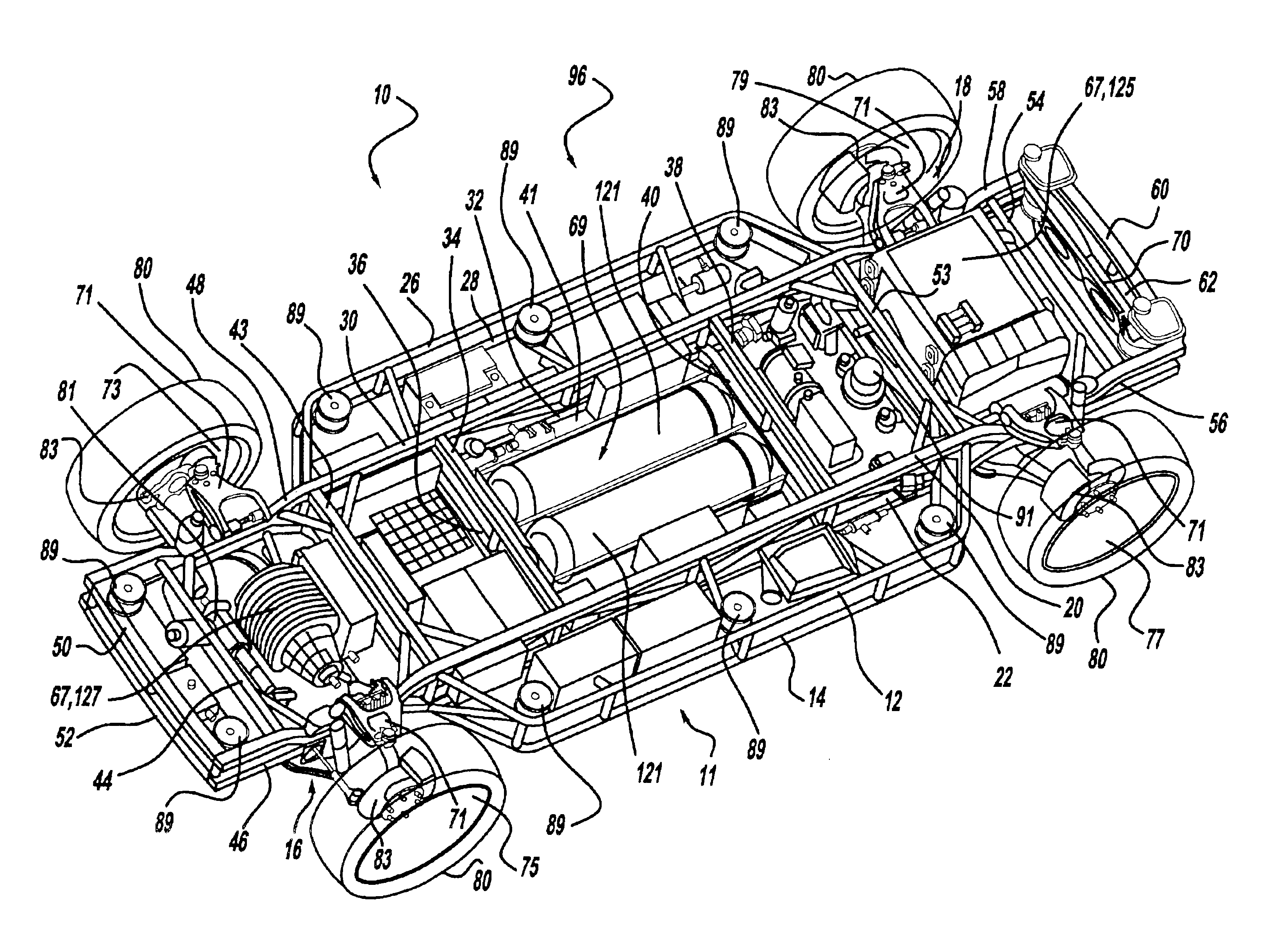
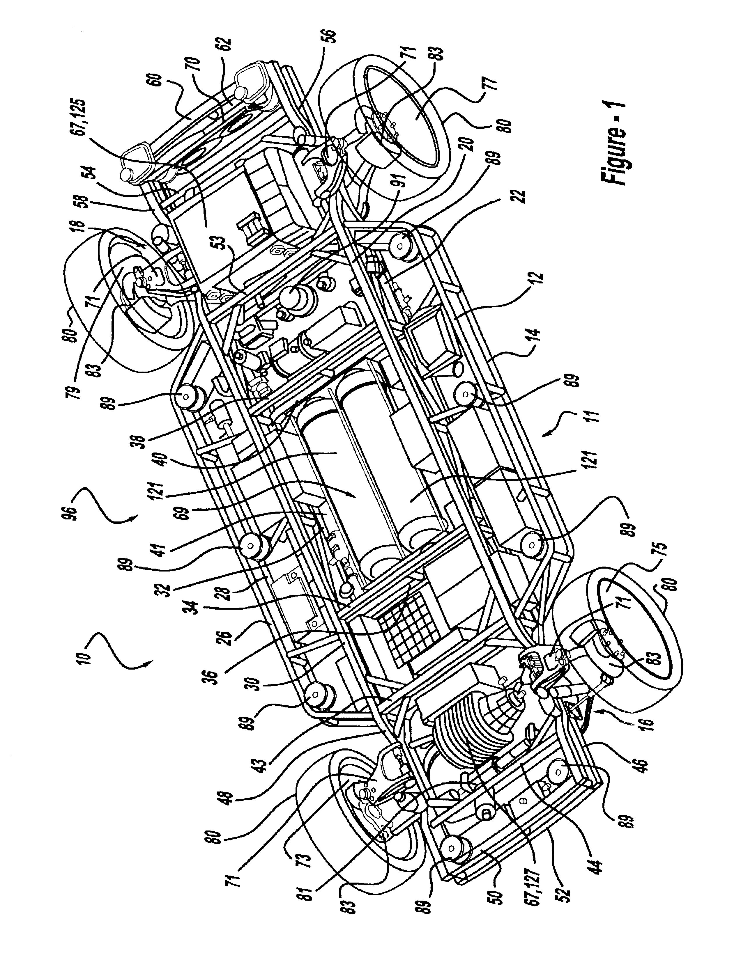
Referring to FIG. 1, a vehicle chassis 10 in accordance with the invention, also referred to as the “rolling platform,” includes a structural frame 11. The structural frame 11 depicted in FIG. 1 comprises a series of interconnected structural elements including upper and lower side structural elements 12 and 14 that comprise a “sandwich”-like construction. Elements 12 and 14 are substantially rigid tubular (or optionally solid), members that extend longitudinally between the front and rear axle areas 16, 18, and are positioned outboard relative to similar elements 20, 22. The front and rear ends of elements 12, 14 are angled inboard, extending toward elements 20 and 22 and connecting therewith prior to entering the axle areas 16, 18. For added strength and rigidity a number of vertical and angled structural elements extend between elements 12, 14, 20 and 22. Similar to the elements 12, 14, 20 and 22, which extend along the left side of the rolling platform 10, a family of structural...


PUM

PropertyMeasurementUnit
heightaaaaaaaaaa
poweraaaaaaaaaa
heightaaaaaaaaaa

Abstract

A method of designing and manufacturing vehicle bodies includes establishing a common, standardized interface system for attaching vehicle bodies to vehicle chassis wherein connection components are arranged in a predetermined spatial relationship on the bodies and chassis to facilitate selective attachment of any of a plurality of different body types to the chassis. A plurality of different bodies are designed and manufactured having different body types and configured to conform to the standardized interface system for attachment to chassis which also conform to the standardized interface system. The vehicle bodies can be produced independently of the chassis. Eliminating the chassis and its hardware from the body manufacturing process can reduce current vehicle manufacturing plant sizes and system complexity. The result is an enabler to produce many vehicle bodies that can be distributed directly to dealers, customers, etc. either with or without a specified rolling platform. Smaller and customized production runs are enabled, as well as localized manufacturing plants, reduced investment costs and faster response time for order to delivery.

Description

TECHNICAL FIELDThe present invention relates to a vehicle body manufacturing process wherein vehicle bodies are produced independently of vehicle chassis in accordance with a common, standardized interface system such that a diverse range of vehicle bodies can be designed and manufactured for distribution directly to dealers, customers, etc. with or without a chassis.BACKGROUND OF THE INVENTIONMobility, being capable of moving from place to place or of moving quickly from one state to another, has been one of the ultimate goals of humanity throughout recorded history. The automobile has likely done more in helping individuals achieve that goal than any other development. Since its inception, societies around the globe have experienced rates of change in their manner of living that are directly related to the percentage of motor vehicle owners among the population.Prior art automobiles and light trucks include a body, the function of which is to contain and protect passengers and the...

Claims


Application Information

Patent Timeline
Patent Type & Authority Patents(United States)
IPC IPC(8): B60G17/015B60G17/0195B60G13/00B60G3/18B60G13/14B60G7/00B60H1/00B60K1/04B60N2/04B60N2/14B60K1/00B60T1/00B60T1/10B60T1/06B60N2/44B60K15/03B62D5/00B60K15/07B62D65/04B60T13/66B62D7/18B60T13/74B62D7/00B60T13/00B62D65/00B62B3/12B62B3/00B60T7/00B60T7/04B60T8/00G06Q30/00B23P6/00B23P21/00B60N2/90B62D21/00G06Q30/06
CPCB60G3/18B60G7/003B60G13/14B60G17/015B60G17/0195B60H1/004B60K1/00B60K1/04B60K15/07B60K41/202B60K41/28B60N2/14B60N2/44B60T1/065B60T1/10B60T7/00B60T7/042B60T8/00B60T13/66B60T13/662B60T13/74B62B3/12B62D5/00B62D7/18B62D63/025B62D65/04G06Q30/06B60L11/1887B23P2700/50B60G2200/10B60G2200/144B60G2200/18B60G2200/44B60G2200/46B60G2200/462B60G2202/40B60G2202/42B60G2204/10B60G2204/11B60G2204/14B60G2204/16B60G2204/20B60G2204/202B60G2206/011B60G2206/0114B60G2206/50B60G2206/99B60G2300/45B60G2300/50B60G2300/60B60G2800/21B60G2800/802B60G2800/90B60G2800/91B60G2800/92B60G2800/963B60K7/0007B60K2001/001B60K2001/005B60K2741/205B60K2741/28B60T2270/82Y10T29/4973Y10T29/49716Y10T29/49904Y10T29/49718Y10T29/49826Y02T90/34B60N2/90B60L58/40Y02T10/70Y02T90/40
Inventor CHERNOFF, ADRIAN B.BORRONI-BIRD, CHRISTOPHER E.SHABANA, MOHSEN D.VITALE, ROBERT LOUIS
Owner GM GLOBAL TECH OPERATIONS LLC
Why Eureka
Try Eureka