Medical Fluid Injection System

a technology of medical fluid and injection system, which is applied in the field of improved injector system, can solve the problems that manual systems typically do not accommodate any safety features, and achieve the effect of preventing backflow of fluid and being convenient to us

Active Publication Date: 2009-06-11
ACIST MEDICAL SYST
View PDF29 Cites 202 Cited by
  • Summary
  • Abstract
  • Description
  • Claims
  • Application Information

AI Technical Summary

Benefits of technology

[0008]According to certain embodiments, there is provided an injection system that uses a disposable cassette providing fluid connections to the injection system. Fluid that is dispensed by the injection system is provided to the patient via the disposable cassette. One or more tubing components are coupled between the injection system and the disposable cassette. Valves, and particularly pinch valves, may be used to prevent flow of fluid to the disposable cassette in certain scenarios, and to also prevent backflow of fluid. The disposable cassette provides fluid connections between the cassette and the injection system, and also provides connections for tubing that may be connected to the patient. The disposable cassette may be a single-use component that is discarded after each patient use.
[0009]According to certain embodiments, there is provided an injection system that provides multiple display devices. In this aspect, a small display device may be provided directly on the injector, while a larger display device (main control panel) may be located remotely from the small display device. The small display device may be used to provide setup information, error and troubleshooting information, and other system information, and it may also be used to obtain certain input from the user, such as bottle or bag size. In one aspect, there is further provided an additional remote display that may be the size of a personal digital assistant (PDA). This additional remote display may be in communication with the main control panel via a wireless connection, according to one embodiment. A physician may utilize this additional remote display with flexibility, because the display is mobile. Due to its size, the additional display is also very portable and convenient to use. In one implementation, the additional display provides both user input capabilities and display output capabilities.
[0011]According to certain embodiments, there is provided an injection system having an improved graphical user interface (GUI) for display within a display device in the system. One aspect also provides customizable area injection buttons, icons for fast navigation, and a range of predefined icons. In some embodiments, the GUI provides an interface for the user during either guided or express setup modes of the system. In these embodiments, the functionality of the GUI may be synchronized with one or more aspects of the contextual lighting. Various other items in the GUT provide an improved interface with the user.

Problems solved by technology

Such manual systems typically do not accommodate any safety features such as the restriction or prevention of injections outside of predetermined injection parameters (such as rate or pressure), and generally do not include active sensors or alarms to detect air bubbles or other hazards.

Method used


Image

  • Medical Fluid Injection System
  • Medical Fluid Injection System
  • Medical Fluid Injection System

Examples


Embodiment Construction

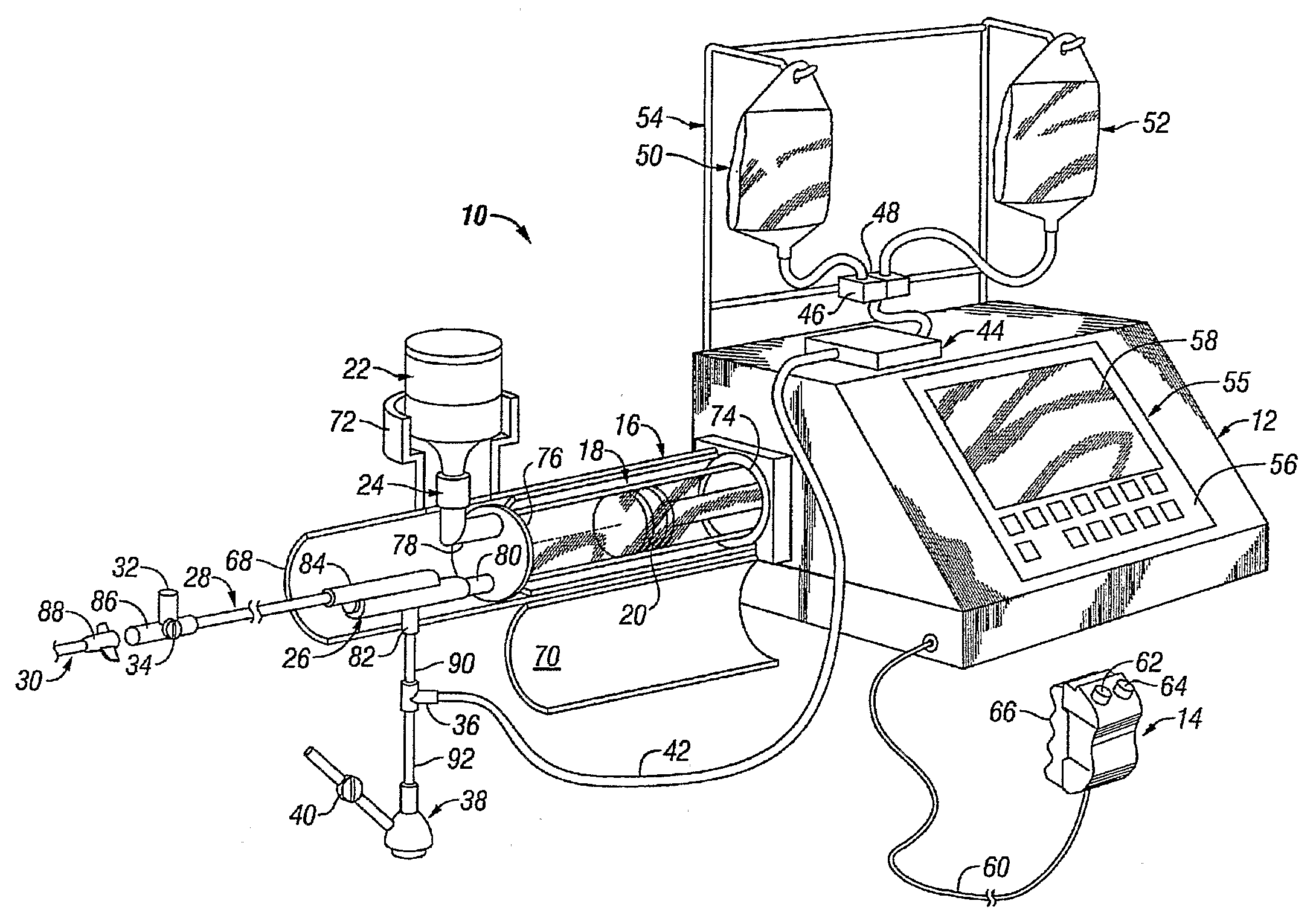
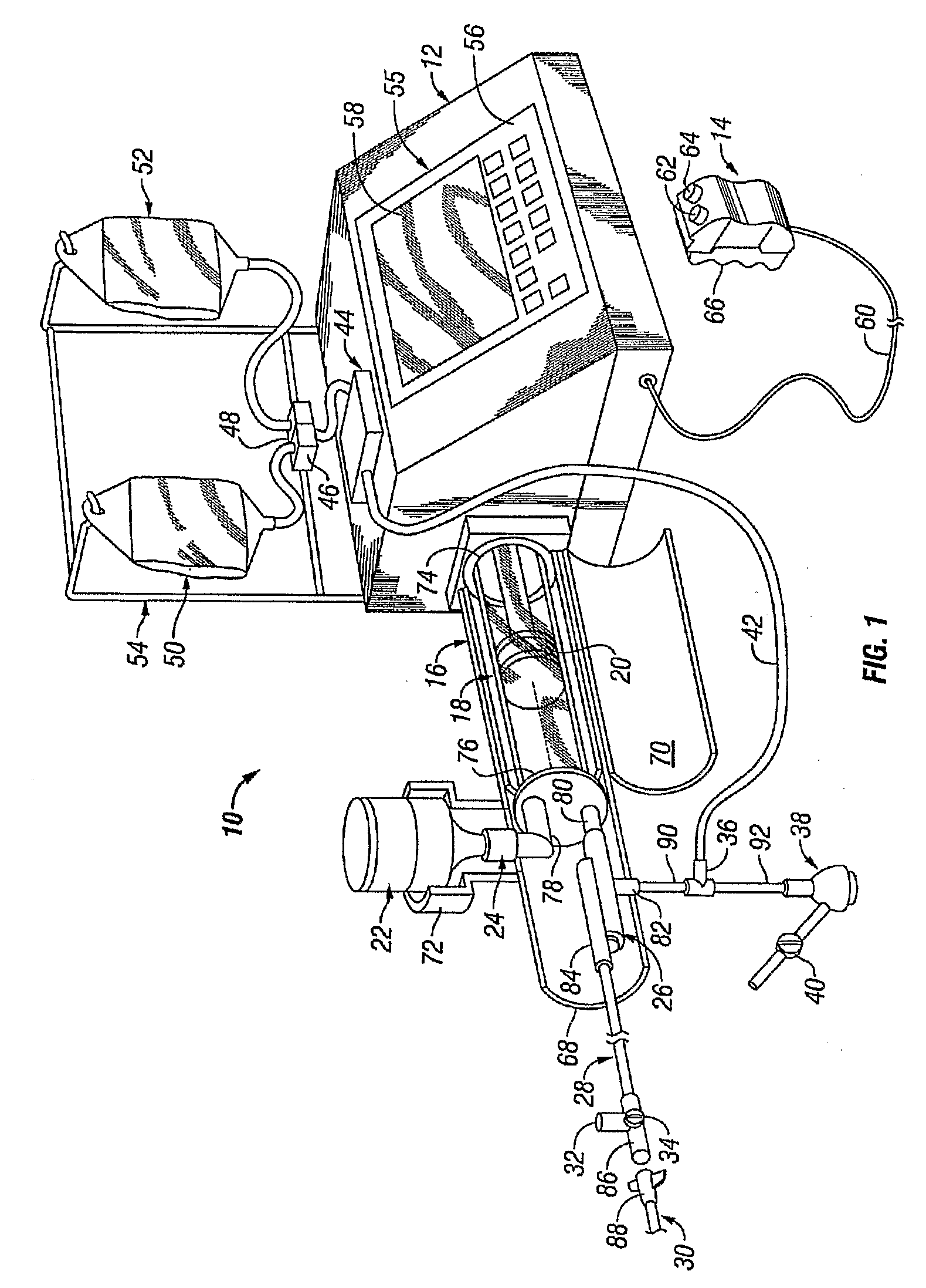
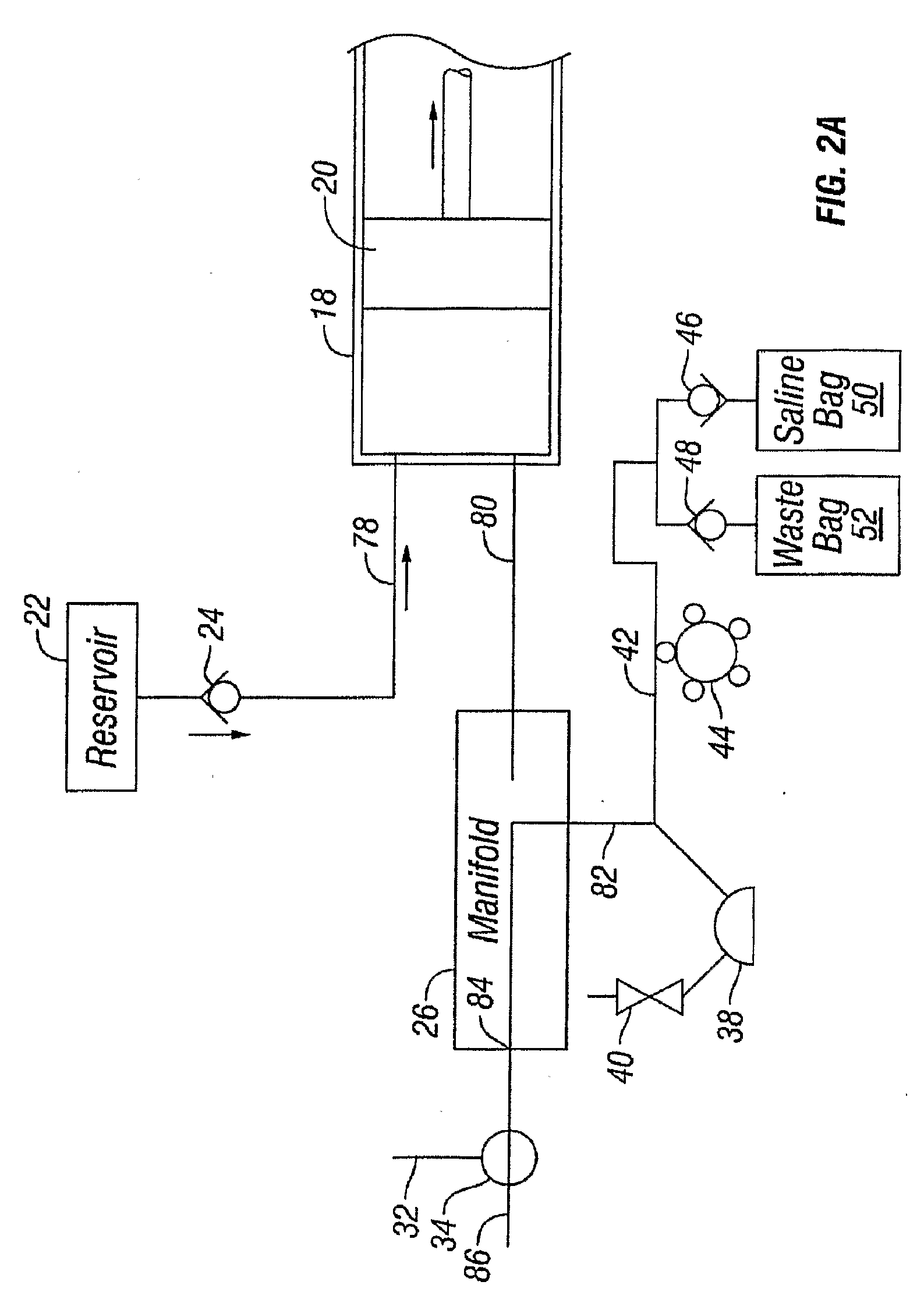
[0058]As will be appreciated upon a more detailed description herein, the principles of various embodiments of this invention can be applied to many different physical configurations of automated injector systems. Example of such systems will be generally described below. Referring to the Drawings, FIG. 1 shows an injector system 10 for injecting radiographic contrast material into a blood vessel under interactive physician control. System 10 includes main console 12, hand held remote control 14, syringe holder 16, syringe body 18, syringe plunger 20, radiographic material reservoir (bottle) 22, one-way valve 24, manifold 26, high pressure tube 28, catheter 30, patient medication port 32, three-way stop-cock 34, T-connector 36, pressure transducer 38, stop-cock 40, tubing 42, peristaltic pump 44, saline check valve 46, waste check valve 48, saline bag 50, waste bag 52, and bag support rack 54.

[0059]Console 12 houses the electrical controls for system 10, together with the motors whi...


PUM


Abstract

One embodiment provides a method of using contextual lighting to assist a user of a medical fluid injection system. In this embodiment, the method includes providing a lighted display in proximity to a component of the injection system during setup of the medical fluid injection system. If the user has properly performed a setup function that is associated with the component of the injection system, the method further comprises providing a first visual indication on the lighted display. If the user has not properly performed the setup function that is associated with the component of the injection system, the method further comprises providing a second visual indication on the lighted display.

Description

FIELD OF THE INVENTION[0001]This application relates generally to an improved injector system for injecting medical fluids, such as radiographic contrast fluids, particularly for angiography.BACKGROUND OF THE INVENTION[0002]Angiography is a procedure used in the diagnosis and treatment of cardiovascular conditions including abnormalities or restrictions in blood vessels, the network of passageways through which blood travels in a human or animal body. During angiography, a radiographic contrast material is injected through a catheter into a vein or artery, which then passes to vascular structures in fluid communication with the vein or artery. When X-rays are passed through the region of the body into which the contrast material is injected, they are absorbed by the contrast material, providing radiographic images of the desired vascular structure(s). The images can be recorded on film or video tape and / or displayed on a fluoroscope monitor. The images can be used for many purposes,...

Claims


Application Information

Patent Timeline
Patent Type & Authority Applications(United States)
IPC IPC(8): A61B6/00G08B21/00G06F3/048G16Z99/00
CPCA61M5/007A61M5/14216A61M5/1452A61M5/16809A61B6/548A61M5/36A61M5/365A61M2005/1403G06F19/3406A61M5/16827G16H40/63G16Z99/00A61M5/00A61M31/00A61B6/504A61B6/481G16H40/00A61M5/16877
Inventor BARRON, TRACICLAUSEN-STUCK, NIELSFISHER, MARKGRACEFFA, JOSPEHHAJICEK, DAVID J.HIEB, MARTIN G.KARAHALIOS, ANASTASIOS G.KENSOK, KARENKIM, ROBERTLUNZER, LAWRENCEMAIERS, MANFREDMENENDEZ, JR., ADOLFOMOHIUDDIN, KHADEROFTEDAHL, RICHARD A.ROOS, VOLKERO'LEARY, JEREMIAH
Owner ACIST MEDICAL SYST
Why Eureka
Try Eureka