Wind spoiler for roofs

a technology for roofs and spoilers, applied in the field of roofs, can solve the problems of affecting the air flow of air, the damage of roofs, and the most devastating types of damage that can occur to a structure, and achieve the effect of reducing the low pressure lifting for

Active Publication Date: 2007-05-24
HOD GINA B +1
View PDF18 Cites 22 Cited by
  • Summary
  • Abstract
  • Description
  • Claims
  • Application Information

AI Technical Summary

Benefits of technology

[0012] For the purpose of summarizing this invention, this invention comprises a wind spoiler that reduces the low pressure area above a roof that occurs as wind flows over the roof, thereby significantly reducing the likelihood that a roof may be damaged by hurricane-force winds.
[0013] The wind spoiler of the invention is an up-standing elongated member that is fastened along the roof line to extend upwardly above the edge of the roof. The elongated member functions as a “wind spoiler” to aerodynamically disrupt or “spoil” the air flow over the roof during high winds conditions. Once the air flow is spoiled, the low pressure area that would otherwise occur as the wind flows over the roof is significantly reduced. The reduction of the low pressure area therefore substantially reduces the lifting force on the roof as air flows over the roof. The likelihood of the wind peeling back the shingles or otherwise causing structural damage to the roof is therefore significantly reduced or eliminated altogether.
[0014] The preferred configuration of the wind spoiler of the invention comprises an L-shaped configuration that is hingely connected to the edge of the roof along the roof line. In its stowed, at rest position, one leg of the L-shaped wind spoiler lays horizontally in alignment with and extending away from the roof line whereas the other leg lies vertically downward against the roof fascia. It is deployed position, the wind spoiler is flipped-back onto the shingles (i.e., rotated on its hinges 180 degrees) such that the horizontal leg is now facing the other direction toward the apex of the roof to lay on top of the leading edge of the shingles and such that the other leg is now extending vertical upward. Thus, in this deployed position, the vertical leg extends above the edge of the roof line to disrupt or spoil the flow of air over the roof thereby significantly reducing the creation of a low pressure area over the roof that would otherwise occur if the air flow was not disrupted. Moreover, in the deployed position, the horizontal leg overlaps the leading edge of the shingles thereby significantly reducing the likelihood of air flowing under the edge of the shingles and peeling them back.
[0016] An important aspect of the preferred embodiment of the wind spoiler of the invention is the fact that the harder the wind blows, the more firmly the horizontal leg presses down on the leading edge of the shingles while in the deployed position to prevent the wind from peeling back the shingles. Similarly, the harder the wind blows, the more the air flow is disrupted by the vertical leg to minimize the likelihood that a damaging low pressure area would be created over the roof.
[0019] Installation of the wind spoiler of the invention is fast and easy. Wind spoiler sections (e.g., 4 foot lengths) are simply attached to the soffit using the above-mentioned hinges, preferably spaced along the fascia in alignment with the roof joists of the roof structure. If a gutter is installed, notches may be cut into the wind spoiler to provide clearance for the gutter supports. Once installed, the wind spoiler of the invention therefore aesthetically appears to be a natural part of the roof edge.

Problems solved by technology

One of the most devastating types of damage that can occur to a structure is the loss of its roof.
During a hurricane or other wind event, wind forcibly flows under a roof and often causes the shingles to peel off.
Further, structural damage to the roof itself is likely to occur.
Once the shingles are peeled from the roof and the roof suffers structural damage, water intrusion occurs, ruining both the structure and its contents.
The wind flowing over the roof therefore tends to not only lift the roof and shingles both by shear catching the edge of the shingles or the plywood of the roof along the bottom and sides of the roof, but also tends to lift the roof structure off the supporting roof joists due to the low-pressure created over the roof as the wind flows over the roof.
However, the prior art clips and braces do not eliminate the cause of the problem; namely, they fail to eliminate the low pressure area on the roof as the wind flows over the roof.

Method used


Image

  • Wind spoiler for roofs
  • Wind spoiler for roofs
  • Wind spoiler for roofs

Examples


Embodiment Construction

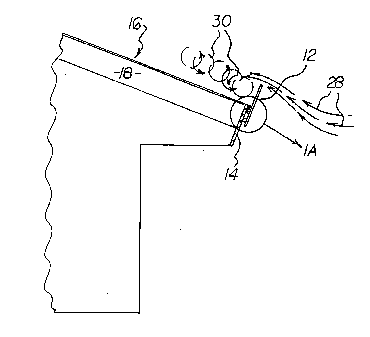
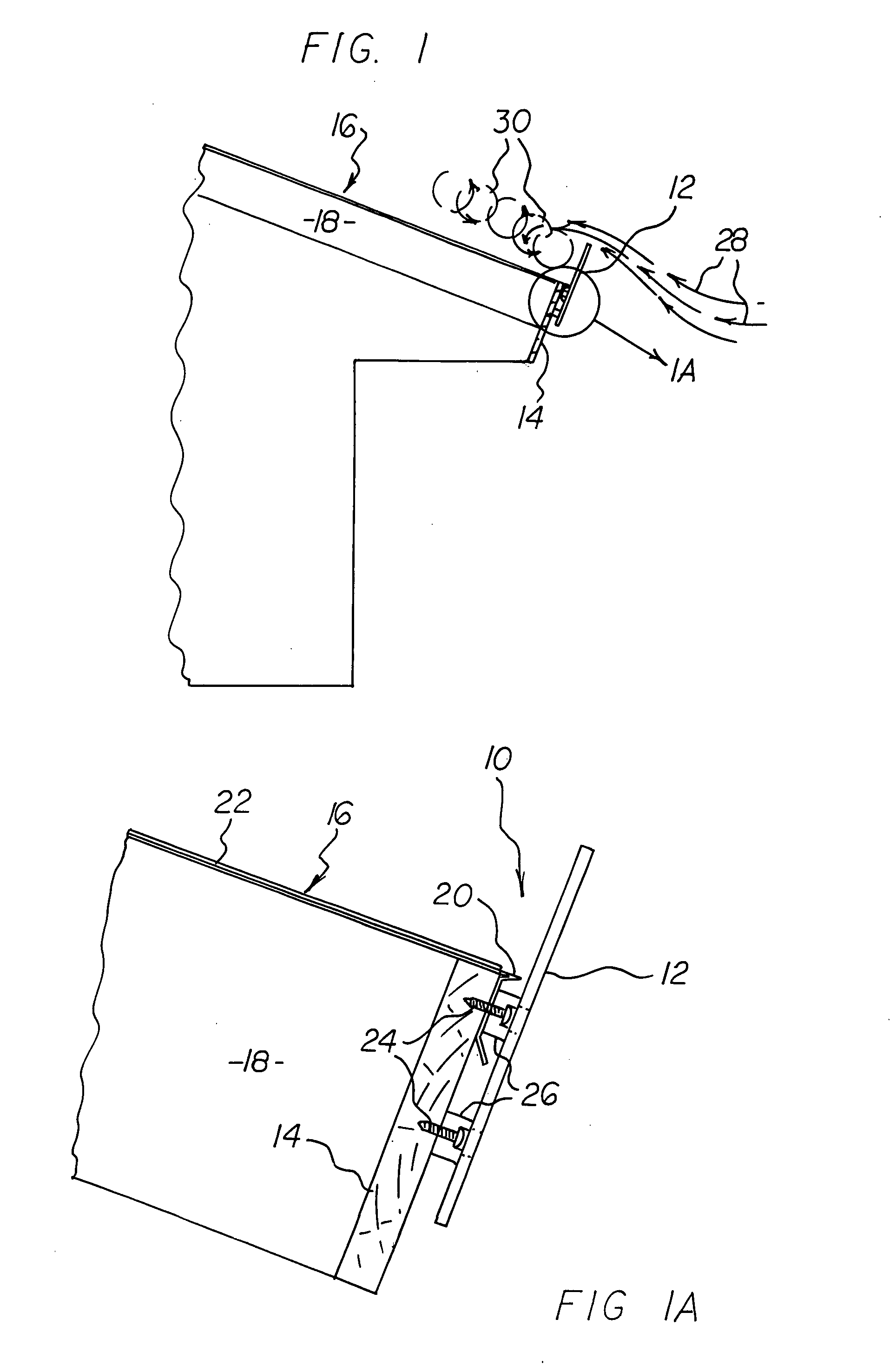
[0033] Referring to FIG. 1, the fixed embodiment of the wind spoiler 10 of the invention comprises a generally flat elongated vertical member 12 that is mounted to the fascia 14 of a roof 16 to extend upwardly above the plane of the roof 16. More particularly, as shown in the partially-expanded view of FIG. 1, a plurality of roof joists 18 are provided to define the plane of the roof 16. The fascia 14 is then nailed to the leading edges of the roof joists 18. A drip edge 20 is then fitted over the uppermost edge of the fascia 14 to direct rainfall to drip from the drip edge 20 instead of the fascia 14 itself. Conventional roofing shingles 22 are installed on the upper surface of the roof 16, typically by nailing.

[0034] The vertical member 12 of the wind spoiler 10 of the invention is mounted to the fascia 14 by suitable fasteners such as screws 24. As shown, the vertical member 12 may be positioned slightly away from the drip edge 20 by means of stand-offs 26 so as to not interfere...


PUM


Abstract

A wind spoiler including a vertical member mounted vertically along a roof of a structure to extend above the plane of the roof for creating turbulence in wind flowing over the roof.

Description

CROSS-REFERENCE TO RELATED APPLICATIONS [0001] This application claims the benefit of provisional application No. 60 / 735,954, filed Nov. 10, 2005, the disclosure of which is incorporated by reference herein.BACKGROUND OF THE INVENTION [0002] 1. Field of the Invention [0003] This invention relates to roofing systems. More particularly, this invention relates to an apparatus and method for reducing the likelihood that a roof may be damaged by hurricane-force winds. [0004] 2. Description of the Background Art [0005] One of the most devastating types of damage that can occur to a structure is the loss of its roof. During a hurricane or other wind event, wind forcibly flows under a roof and often causes the shingles to peel off. Further, structural damage to the roof itself is likely to occur. Once the shingles are peeled from the roof and the roof suffers structural damage, water intrusion occurs, ruining both the structure and its contents. [0006] The roof of a building is a large lift...

Claims


Application Information

Patent Timeline
Patent Type & Authority Applications(United States)
IPC IPC(8): B61D17/02
CPCE04D13/00E04D13/076
Inventor KAISER, BRUCE A.OLDHAM, JAMES R.
Owner HOD GINA B
Why Eureka
Try Eureka