Casing for a modular socket

Inactive Publication Date: 2006-02-21
HUANG HUANG CHOU
View PDF17 Cites 12 Cited by
  • Summary
  • Abstract
  • Description
  • Claims
  • Application Information

AI Technical Summary

Benefits of technology

[0009]The primary objective of the present invention is to provide an improved modular socket casing which has a rear plate able to secure engagement with two adjacent side walls to avoid possibility of detachment between the rear plate and the side walls.

Problems solved by technology

Therefore, the user of this conventional modular socket casing often finds this drawback annoying as the casing can not fulfill the requirements.

Method used


Image

  • Casing for a modular socket
  • Casing for a modular socket
  • Casing for a modular socket

Examples


Embodiment Construction

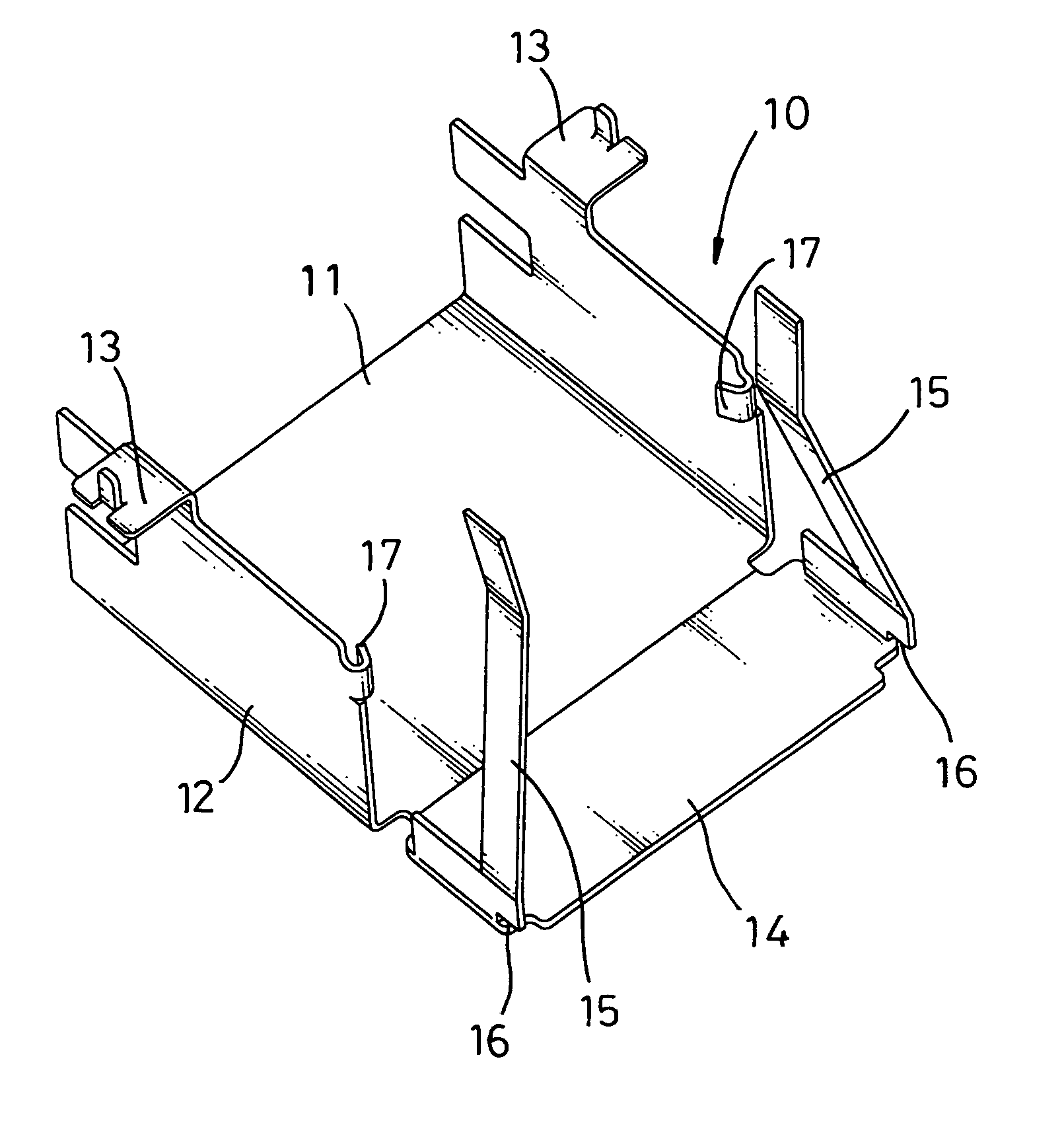
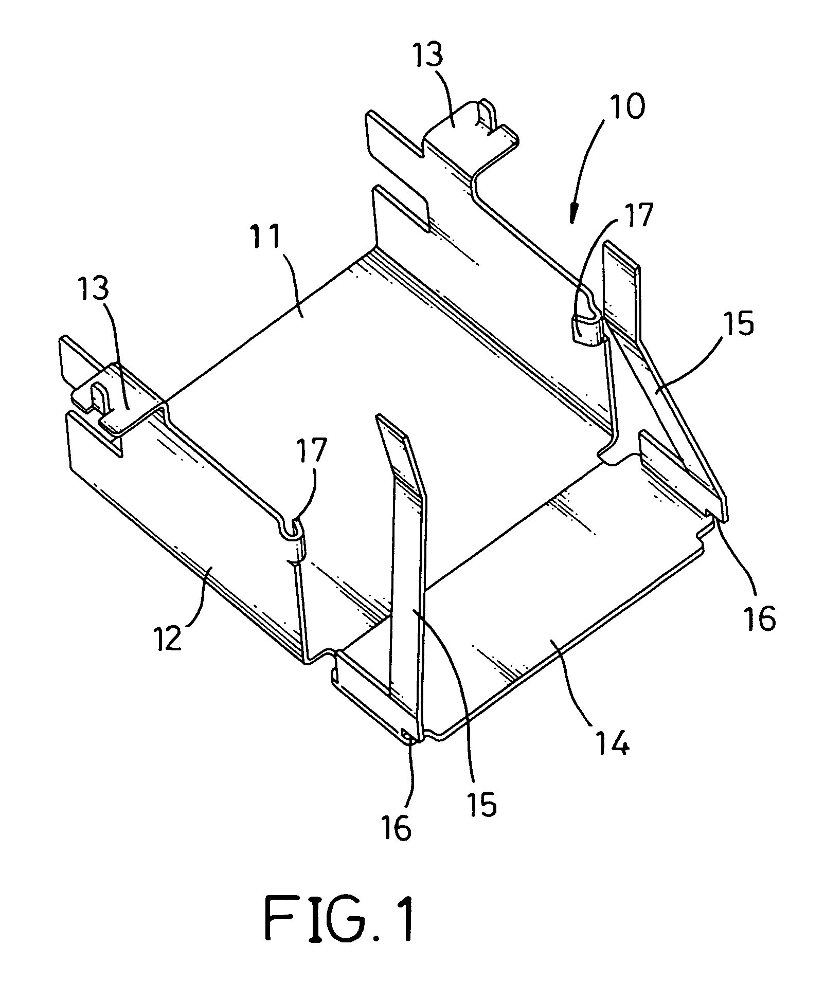
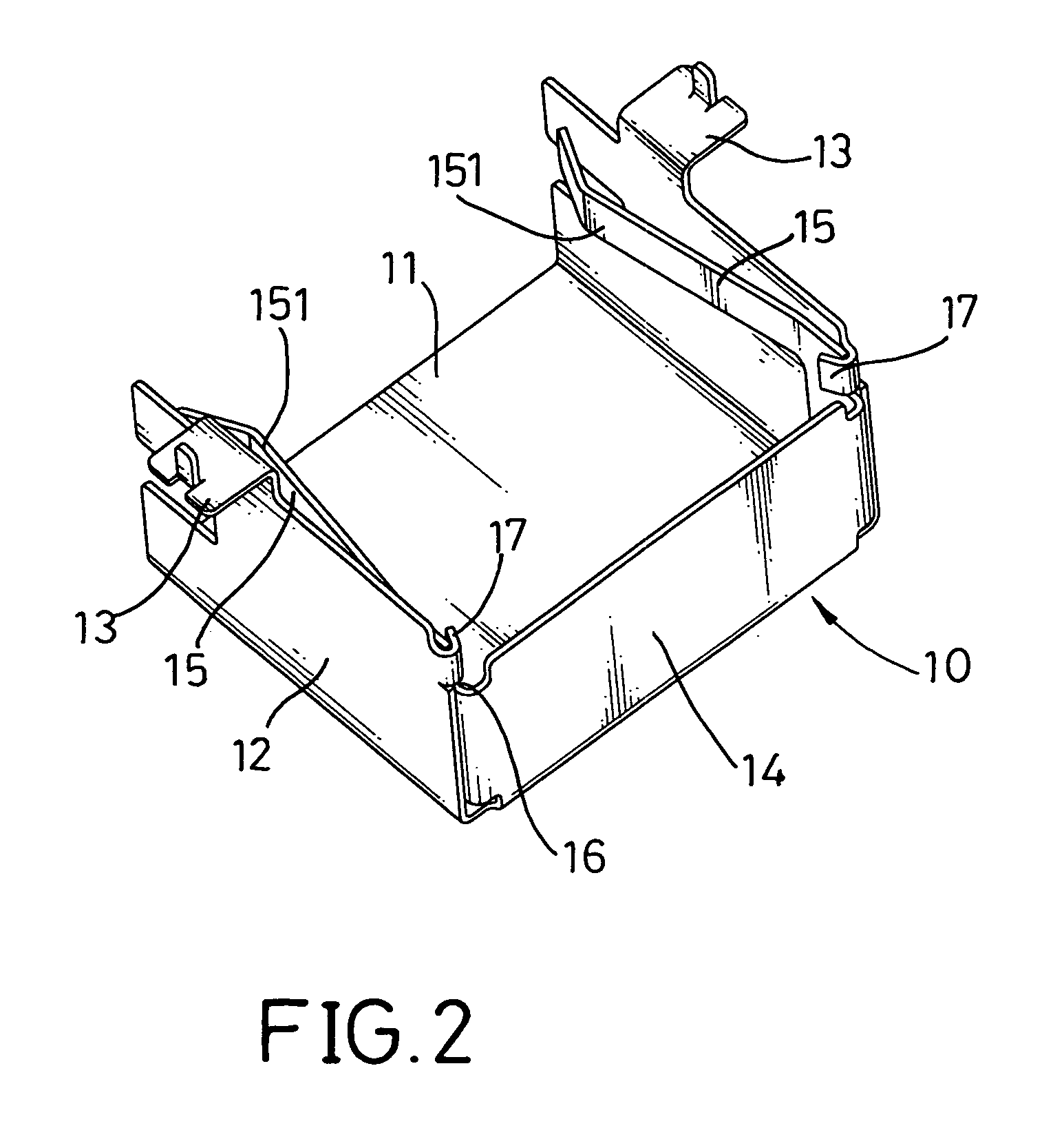
[0016]With reference to FIGS. 1 and 2, the modular socket casing (10) in accordance with the present invention is made of a sheet of metal and has a bottom face (11), two opposed side walls (12) each extending upright from a side face of the bottom face (11) and having a bend (13) extending out from a peripheral edge of the side wall (12) and a rear plate (14) extending from a side face of the bottom face (11) and sandwiched between the two side walls (12). The rear plate (14) has two arms (15) respectively and oppositely extending from a side face of the rear plate (14) to face each other. A cutout (16) is defined at a joint between each arm (15) and the side face of the rear plate (14). Furthermore, each side wall (12) is provided with a hook (17) formed on an inner face of the side wall (12) to correspond to the cutout (16).

[0017]When the casing (10) of the present invention is assembled, the rear plate (14) is first folded to allow each hook (17) to be received in the correspond...


PUM


Abstract

A modular socket casing includes a bottom face, two side walls respectively and oppositely extending from a side of the bottom face, each side wall having a bend extending from a peripheral edge of the side wall and a hook formed on a side face of the side wall and a rear plate integrally extending from a side of the bottom face and having two opposed arms each extending from a side of the rear plate and a cutout defined at a joint between the arm and the rear plate to correspond to and receive therein the hook after the rear plate is folded such that the casing is formed.

Description

BACKGROUND OF THE INVENTION[0001]1. Field of the Invention[0002]The present invention relates to a casing, and more particularly to the casing for a modular socket used in a telephone line connector.[0003]2. Description of Related Art[0004]With reference to FIGS. 4 and 5, a conventional casing (30) of a modular socket is made of a sheet of metal and has a bottom face (31), two side walls (32) oppositely extending upright from the bottom face (31) and a rear plate (34) integrally formed with the bottom face (11) and sandwiched between the two side walls (32).[0005]Each side wall (32) is provided with a bend (33) extending outward from a peripheral edge of the side wall (32) and a boss (37) formed on an inner face of the side wall (32). The rear plate (34) has two opposed side plates (35) each formed on a side face of the rear plate (34) and having a through hole (36) defined through a face of the side plate (35) to correspond to the boss (37).[0006]When the casing is assembled, the r...

Claims


Application Information

Patent Timeline
IPC IPC(8): H01R13/648
CPCH01R13/65802H01R24/62H01R13/6582
Inventor HUANG, HUANG-CHOU
Owner HUANG HUANG CHOU
Why Eureka
Try Eureka