Laminating machine

Inactive Publication Date: 2014-03-25
KING MICHAEL T
View PDF4 Cites 1 Cited by
  • Summary
  • Abstract
  • Description
  • Claims
  • Application Information

AI Technical Summary

Benefits of technology

The laminating machine described in this patent makes it easy and efficient for teachers or secretaries to replace laminating film rolls. It ensures correct and rapid installation of the film from both the upper and lower rollers onto the heated laminating rollers of the machine. It also prevents the adhesive layer of the film from getting in contact with the heated roller and causing unwinding of the film. Overall, this machine simplifies the lamination process and improves efficiency.

Problems solved by technology

However, correctly threading the films from the film supply rollers has proved difficult for many classroom instructors, especially in aligning the webs of film with each other as they are inserted into the machine and thereafter placing them on the heated laminating rollers without having the adhesive coated side of the film contacting those rollers.

Method used


Image

  • Laminating machine
  • Laminating machine
  • Laminating machine

Examples


Embodiment Construction

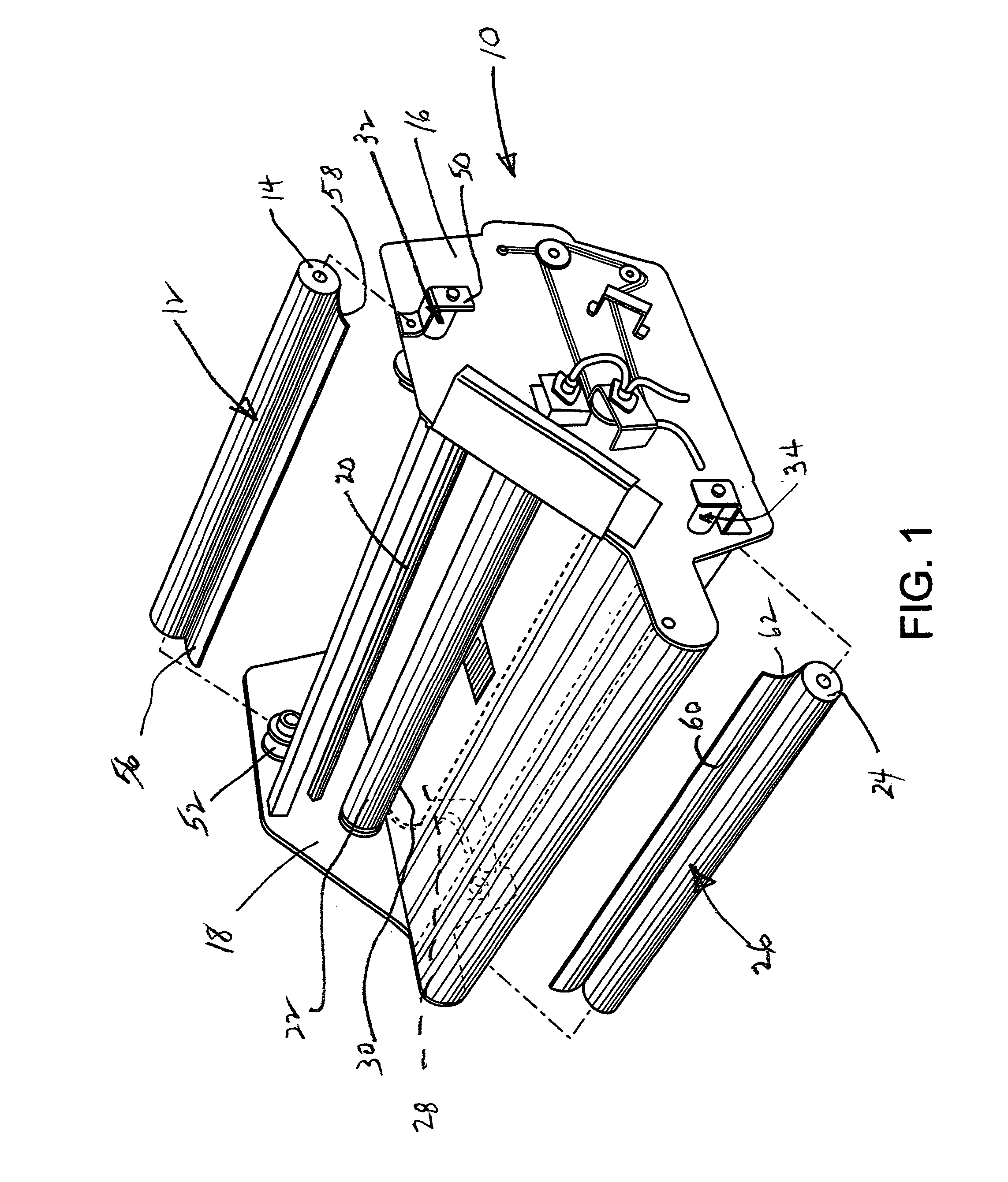
[0021]Elements of the improved laminating machine 10 of this invention are shown in perspective in FIG. 1. An upper laminating film 12 is shown wound around upper laminating film supply roller 14, and the roller 14 is shown in position to be installed in the machine 10 between side frames 16 and 18. The path of film 12, as shown in FIG. 5, extends below an idler roller 20 and around a heated upper laminating roller 22. A lower laminating film supply roller 24 which carries a supply of lower laminating film 26 is shown in position to be installed in the machine 10 between the side frames 16 and 18. The path of the lower laminating film 26 is similar to the path of the upper laminating film 12 except that lower laminating film 26 extends around heated lower laminating roller 28. The upper laminating film 12 and the lower laminating film 26 meet at a nip 30 between the heated upper laminating roller 22 and the heated lower laminating roller 28. An object to be laminated (not shown) is ...


PUM


Abstract

A laminating machine for making sheet laminations using a thermal laminating film is disclosed which protects the film from being mounted in the machine in a manner that will expose its adhesive side to the heated laminating rollers in the machine. The film is stored on upper and lower supply rollers in the machine. Each supply roller is engaged at one end by a forward end of a rotatable piston disposed in a variable-length spring operated chuck. A stem attached to the forward end of the piston extends rearwardly from the forward end and away from the roller into a cylindrically enclosed body portion of the chuck. There the stem is engaged by a one-way needle bearing which permits the film to be unwound from the supply roller only in one direction, thus permitting only the non-adhesive side of the film to contact the machine's heated laminating roller.

Description

[0001]This is a non-provisional application which claims the filing date of the same inventor's provisional application Ser. No. 61 / 632,539, filed in the United States Patent and Trademark Office on Jan. 26, 2012.[0002]This invention relates to improvements in machines for covering pages of copy material with film by encasing them between layers of film. More particularly, it relates to introducing upper and lower layers of laminating film wound on supply rollers into a laminating machine easily in registration with each other and insuring that the adhesive layers of the laminating film on each of the rollers does not contact the heated film laminating rollers in the machine as the film from each laminating film supply roller is unwound.[0003]Except for the provisional application just referred to, there are no patent applications related to this one. This application is not subject to any federally sponsored research or development or to any joint research agreement. The inventor i...

Claims


Application Information

Patent Timeline
IPC IPC(8): B32B37/00
CPCB32B37/0053B32B2037/0061B32B37/12B32B37/00Y10T156/1741
Inventor KING, MICHAEL, T.
Owner KING MICHAEL T
Why Eureka
Try Eureka