Cartridge embolic protection filter and methods of use

a technology of embolism protection and filter, which is applied in the field of embolism protection devices, can solve the problems of affecting the placement of the device within the tortuous vasculature, and enlarged the profil

Active Publication Date: 2006-02-21
BOSTON SCI SCIMED INC
View PDF240 Cites 67 Cited by
  • Summary
  • Abstract
  • Description
  • Claims
  • Application Information

AI Technical Summary

Problems solved by technology

These catheters often require relatively large chambers to transport the collapsed filter within the body, resu...

Method used


Image

  • Cartridge embolic protection filter and methods of use
  • Cartridge embolic protection filter and methods of use

Examples


Embodiment Construction

[0010]The following description should be read with reference to the drawings, in which like elements in different drawings are numbered in like fashion. The drawings, which are not necessarily to scale, depict selected embodiments and are not intended to limit the scope of the invention. Although examples of construction, dimensions, materials and manufacturing processes are illustrated for the various elements, those skilled in the art will recognize that many of the examples provided have suitable alternatives that may be utilized.

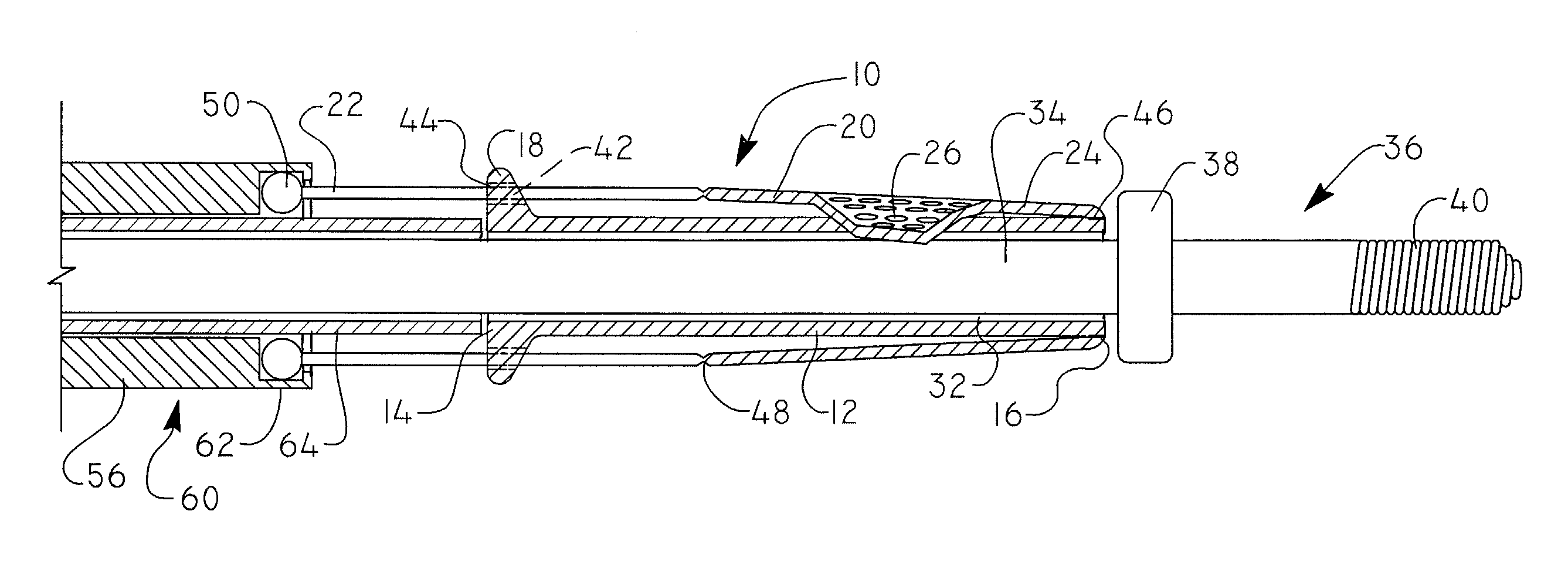
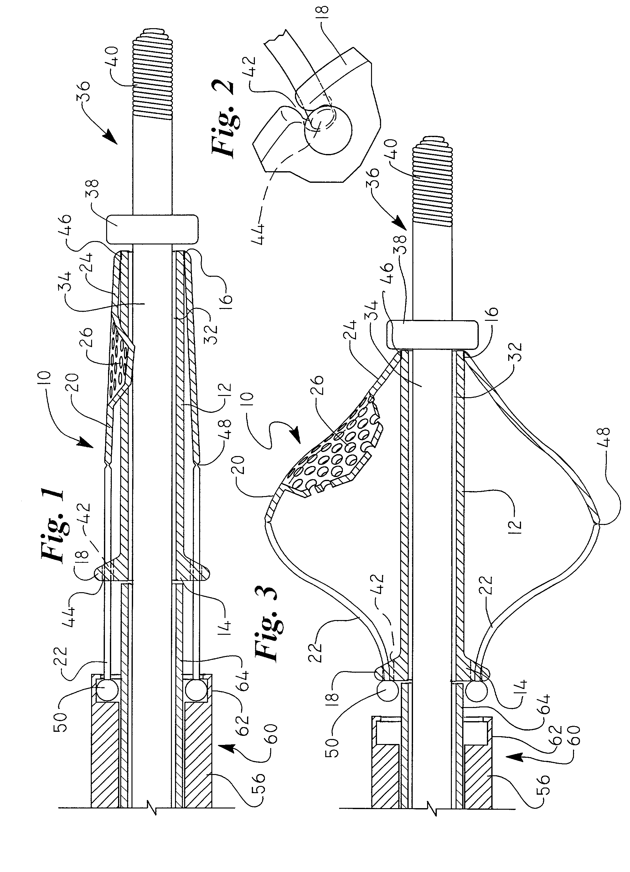
[0011]FIG. 1 is a cross-sectional view of an embolic protection filter 10 in accordance with an exemplary embodiment of the present invention. Embolic protection filter 10 includes a filter frame 12, a plurality of retaining collars 18, a plurality of expandable struts 20, and a filter mesh 26 attached to a distal section 24 of the expandable struts 20. The expandable struts 20, which are discussed in greater detail below, are biased to move between a c...


PUM


Abstract

An embolic protection filter having a reduced profile for placement within a body lumen is disclosed. One embodiment has an embolic protection filter that includes a filter frame slidably and rotationally disposed along a guidewire, a plurality of retaining collars coupled to a proximal end of the filter frame, a plurality of expandable struts each having a proximal section adapted to slide within a corresponding retaining collar, and a filter mesh coupled to a distal section of the expandable struts for filtering embolic debris.

Description

FIELD OF THE INVENTION[0001]The present invention relates generally to the field of embolic protection devices. More specifically, the present invention pertains to cartridge embolic protection filters having a reduced profile.BACKGROUND OF THE INVENTION[0002]Embolic protection filters are frequently used in conjunction with other therapeutic devices to filter embolic material such as plaque or thrombus from the blood stream. In a typical application such as percutaneous transluminal angioplasty (PTA) or percutaneous transluminal coronary angioplasty (PTCA), a collapsed filter is advanced along a guidewire to a location distal a lesion to be dilated. After the filter has been positioned and deployed within the vessel, an angioplasty catheter containing an angioplasty balloon is advanced along the guidewire and positioned proximal the lesion. The angioplasty balloon is then inflated, forcing the embolic material to become dislodged from the walls of the vessel and flow downstream, wh...

Claims


Application Information

Patent Timeline
IPC IPC(8): A61M29/00A61F2/01
CPCA61F2/013A61F2002/015A61F2230/0006A61F2002/018A61F2230/0076A61F2/01
Inventor ESKURI, ALANHANSEN, JAMES G.
Owner BOSTON SCI SCIMED INC
Why Eureka
Try Eureka