Compact miter apparatus

a technology of compact miter and miter joint, which is applied in the direction of measuring gauges, metal working apparatus, printing, etc., can solve the problems of defective pieces that cannot be used for the intended purpose, the appearance of the miter joint is sloppy or unsightly, and the use of problems that are associated with their us

Inactive Publication Date: 2006-02-28
BELLSOUTH INTPROP COR
View PDF10 Cites 6 Cited by
  • Summary
  • Abstract
  • Description
  • Claims
  • Application Information

AI Technical Summary

Benefits of technology

[0007]It is an object of the present invention to provide an imp...

Problems solved by technology

For example, if the pieces join each other to form a right angle, each piece must be mitered along a 45° angle; any significant deviation from the desired angle when cutting either piece will result at best in a miter joint having a sloppy or unsightly appearance, and at worst in a defective piece that cannot be used for the intended purpose.
Although miter boxes are commonplace for use by carpenters, problems are associated with their use.
For one thing, commercially-available miter box...

Method used


Image

  • Compact miter apparatus
  • Compact miter apparatus
  • Compact miter apparatus

Examples


Embodiment Construction

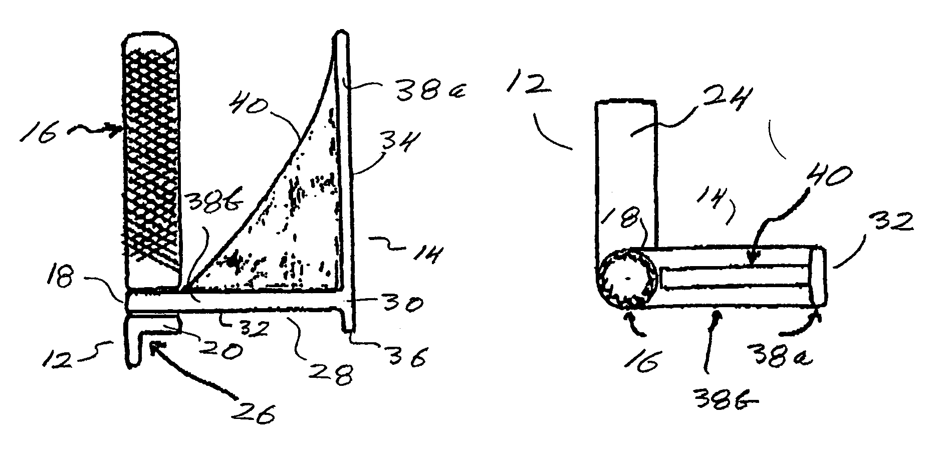
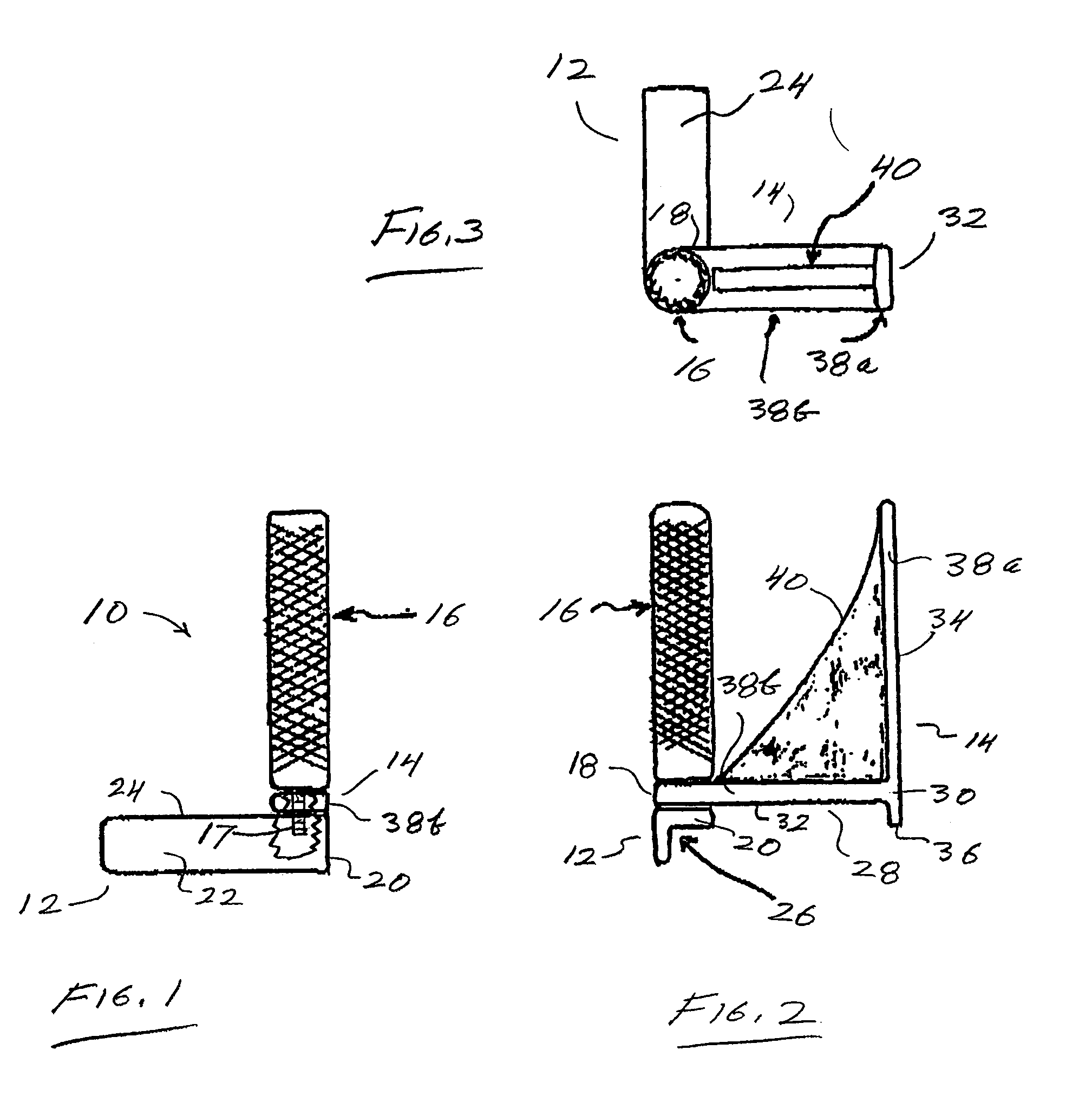
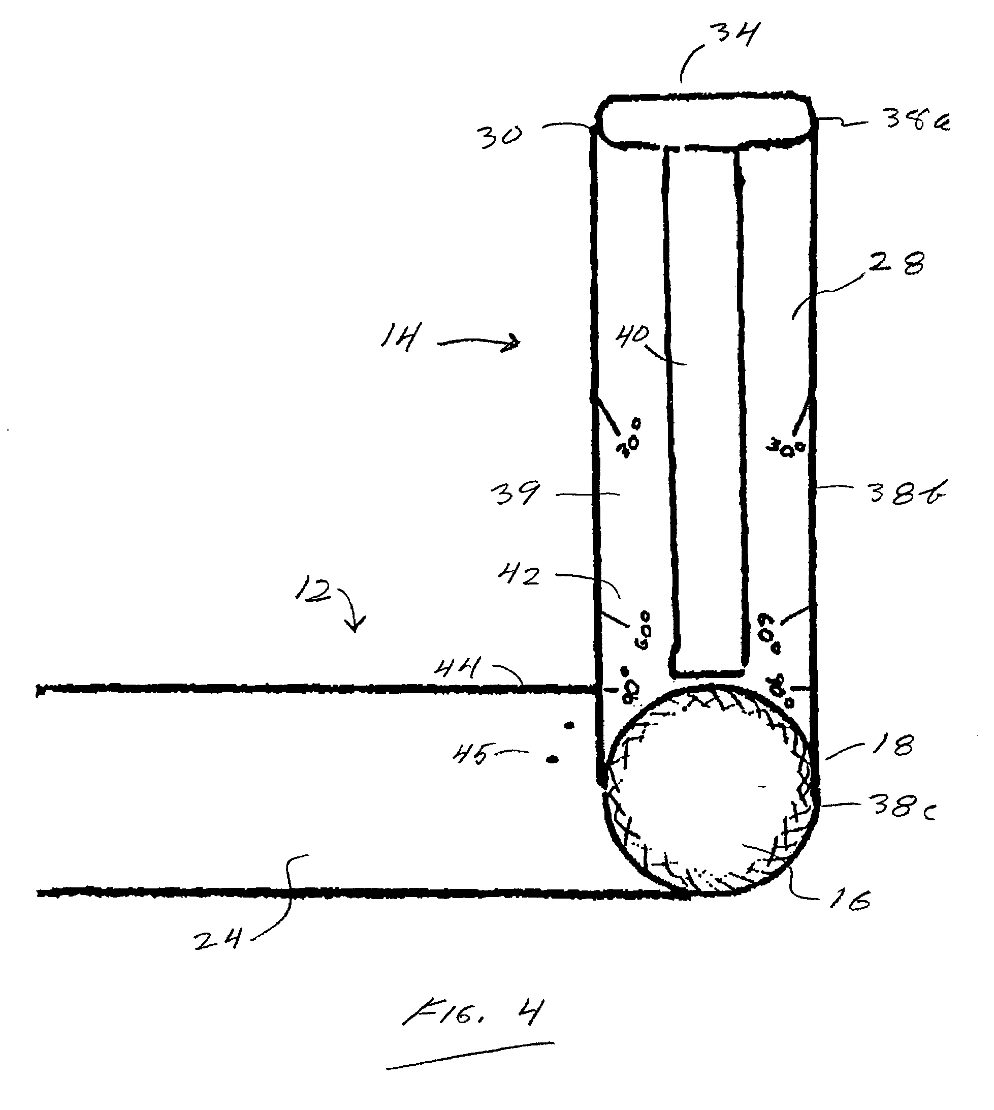
[0023]Turing first to FIGS. 1–3, a compact miter apparatus 10 according to a disclosed embodiment of the invention comprises a base 12 and a guide member 14 pivotably attached to one end of the base 12. The pivotable attachment between the base 12 and the guide member 14 is provided in the disclosed embodiment by a knurl 16 having a threaded portion 17 of reduced diameter, extending through an opening provided at an end 18 of the guide member 14 proximal to an end 20 of the base. That end 17 of reduced diameter makes threaded engagement with a mating opening in or through the base 12 adjacent the end 20. (The term “knurl” is used herein, unless the context indicates otherwise, in the meaning of a knob or small protuberance.)

[0024]The base 12 of the disclosed embodiment has a front portion 22 joining a top portion 24 to provide an L-shaped interior angle defining a seat 26, best seen in FIG. 2. The disclosed configuration of the base 12 thus adapts the miter apparatus 10 to fit again...


PUM


Abstract

A miter apparatus is for making beveled cuts in a workpiece such as a board or the like. A base defines a seat for placing against an edge of the workpiece, and a guide member is pivotably attached to the base for adjustment to any desired angle of a beveled cut. Side surfaces of the guide member provide a bearing surface against which one side of a conventional handsaw may move to guide the saw while cutting the workpiece at the desired angle. A knob selectably secures the to guide member the base, and a surface on the knob provides an additional bearing surface for guiding the saw.

Description

FIELD OF THE INVENTION[0001]This invention relates in general to apparatus for guiding miter cuts in a workpiece, and relates in particular to relatively compact apparatus for assisting miter cuts in workpieces such as boards or the like.BACKGROUND OF THE INVENTION[0002]A miter joint is a joint made by beveling each of two surfaces to be joined, for example at a 45° angle, to form a corner the included angle of which is the sum of the two bevel angles. Two commonplace examples of miter joints are found in the trim molding placed at the upper ends of walls in many rooms, and at the corners of picture frames. Miter joints provide a finished and esthetically-pleasing appearance and may improve the structural strength or rigidity of the joined pieces in some applications.[0003]In order to produce an effective miter joint, it is necessary to cut the pieces being joined along a proper angle. For example, if the pieces join each other to form a right angle, each piece must be mitered along...

Claims


Application Information

Patent Timeline
IPC IPC(8): B43L7/12
CPCB23Q9/005G01B3/56B27G5/02B26B29/06
Inventor DIGGLE, III, FREDERICKRIVERS, PAUL
Owner BELLSOUTH INTPROP COR
Why Eureka
Try Eureka