Power blocks

a technology of power blocks and power blocks, applied in the direction of screws, threaded fasteners, bolts, etc., can solve the problems of compromising the sealing capability of the interface between the carrier housing and the fuel economy of large vehicles such as trucks, and achieve the effect of maximum sealing for

Inactive Publication Date: 2006-02-28
DANA HEAVY VEHICLE SYSTEMS GROUP LLC
View PDF20 Cites 15 Cited by
  • Summary
  • Abstract
  • Description
  • Claims
  • Application Information

AI Technical Summary

Benefits of technology

[0010]To make manifest freedom to utilize lighter differential housing/axle housing combinations for large vehicles, a revelation of the present invention is brought forth. In a preferred embodiment the present invention brings forth the liberty of using lighter differential housings and differential housing/axle housing combination for truck-type vehicles. The present invention includes a support member for the differential carrier housing. The support memb

Problems solved by technology

The fuel economy of large vehicles, such as trucks, has always been an economic issue.
Unfortunately, in certain conditi

Method used


Image

  • Power blocks
  • Power blocks
  • Power blocks

Examples


Embodiment Construction

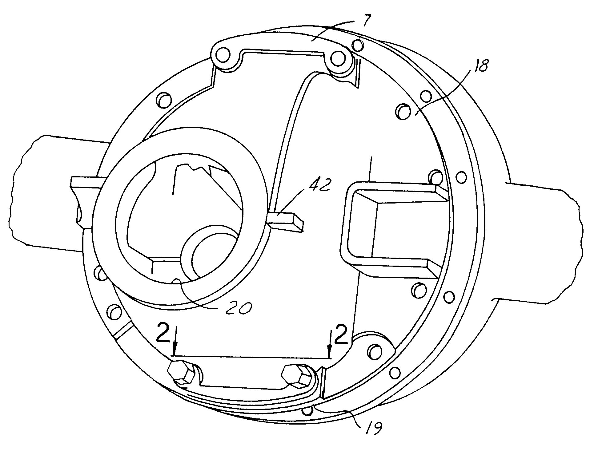
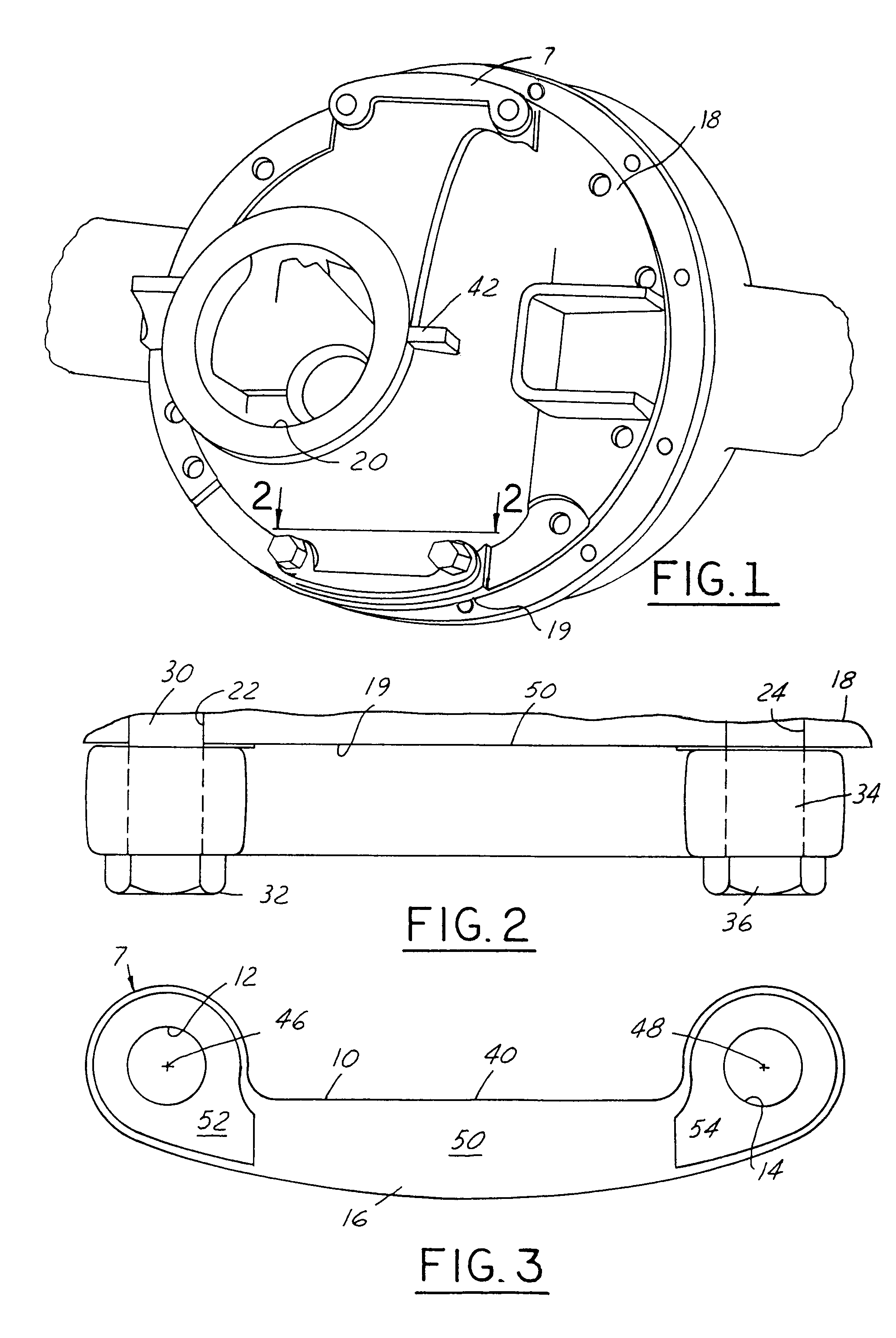
[0021]Referring now to FIG. 1 a support member 7 for differential carrier housing is provided. The support member 7 has a first aperture 12. The support member also has a second aperture 14. The support member 7 has a body extending between the apertures 12 and 14. The support member has an inboard side 16. The inboard side 16 of the support member faces a differential carrier housing 18. The differential carrier housing 18 has an opening 20 that receives a universal joint (not shown) which is connected with the most rearward drive shaft (not shown). The differential carrier housing 18 provides cover and support for the differential carrier (not shown). The differential carrier housing has a peripheral flange 19. The differential housing flange 19 has an aperture 22. The aperture 22 is aligned with aperture 12 provided in the support member 7. The aperture 22 is also aligned with another aperture provided along a perimeter of the central opening of the axle housing (not shown). The ...


PUM


Abstract

A support member for a differential carrier housing, including a body having first and second apertures configured to align with corresponding apertures on one side of a flange of a carrier housing and configured to receive fasteners extending through the apertures in the carrier housing and corresponding apertures in an axle housing disposed on the other side of the carrier housing, the body extending between the apertures in the carrier housing.

Description

BACKGROUND OF THE INVENTION[0001]1. Field of the Invention[0002]The present invention relates to large trucks wherein the differential of the vehicle is mounted to an axle rather than to the vehicle body, and more particularly, to large trucks wherein the differential carrier housing is sealably mated with a large opening in the axle housing.[0003]2. Discussion of Related Art[0004]Most large vehicles include a wheeled frame that is powered by a front mounted engine. The engine is torsionally connected with a transmission. The output of the transmission is connected with a front drive shaft. A first universal joint is connected between the output shaft of the transmission and a front end of the front drive shaft. A second universal joint is connected between a second end of the front drive shaft and a rear drive shaft. A third universal joint is connected between the rear drive shaft and an input shaft of the differential carrier.[0005]The differential carrier is mounted to the rear ...

Claims


Application Information

Patent Timeline
IPC IPC(8): B60K17/00F16H57/02F16H57/037
CPCF16H57/037F16H2057/02091F16H2057/0206F16H2057/02052
Inventor POLLOCK, PAULTHOMPSON, DARRELL D.
Owner DANA HEAVY VEHICLE SYSTEMS GROUP LLC
Why Eureka
Try Eureka