Non-sliding gate valve

a gate valve and non-sliding technology, applied in the direction of valve arrangements, basic electric elements, electrical apparatus, etc., can solve the problems of increasing the number of components, complicated operation, and complex structure, and achieve the effects of preventing the generation of abrasion powder, simple operation mechanism, and large sealing for

Active Publication Date: 2013-05-09
SMC CORP
View PDF2 Cites 15 Cited by
  • Summary
  • Abstract
  • Description
  • Claims
  • Application Information

AI Technical Summary

Benefits of technology

[0019]In this manner, according to the gate valve of the present invention, since the valve plate is moved vertically with respect to the valve seat surface and moves the valve seal toward and away from the valve seat surface, generation of abrasion powder is reliably prevented without causing friction between the valve seal and the valve seat surface or without allowing the valve seal to rotate within the mounting groove.
[0020]In addition, since the opening and closing operation of the valve plate is realized by a direct advance movement of the air cylinder by a simple mechanism using the cam interposed between the drive rod and the valve shaft, the structure of the operating mechanism is simple, less number of components is needed, and a large sealing force is provided.

Problems solved by technology

However, the gate valve disclosed in Patent Document 1 has disadvantages in that the number of components is increased and the structure is complicated, so that the operation is complicated since a mechanism for moving the valve plate vertically with respect to the valve seat surface is configured by combining a plurality of the links, cam followers, and guide grooves.

Method used


Image

  • Non-sliding gate valve
  • Non-sliding gate valve
  • Non-sliding gate valve

Examples


first embodiment

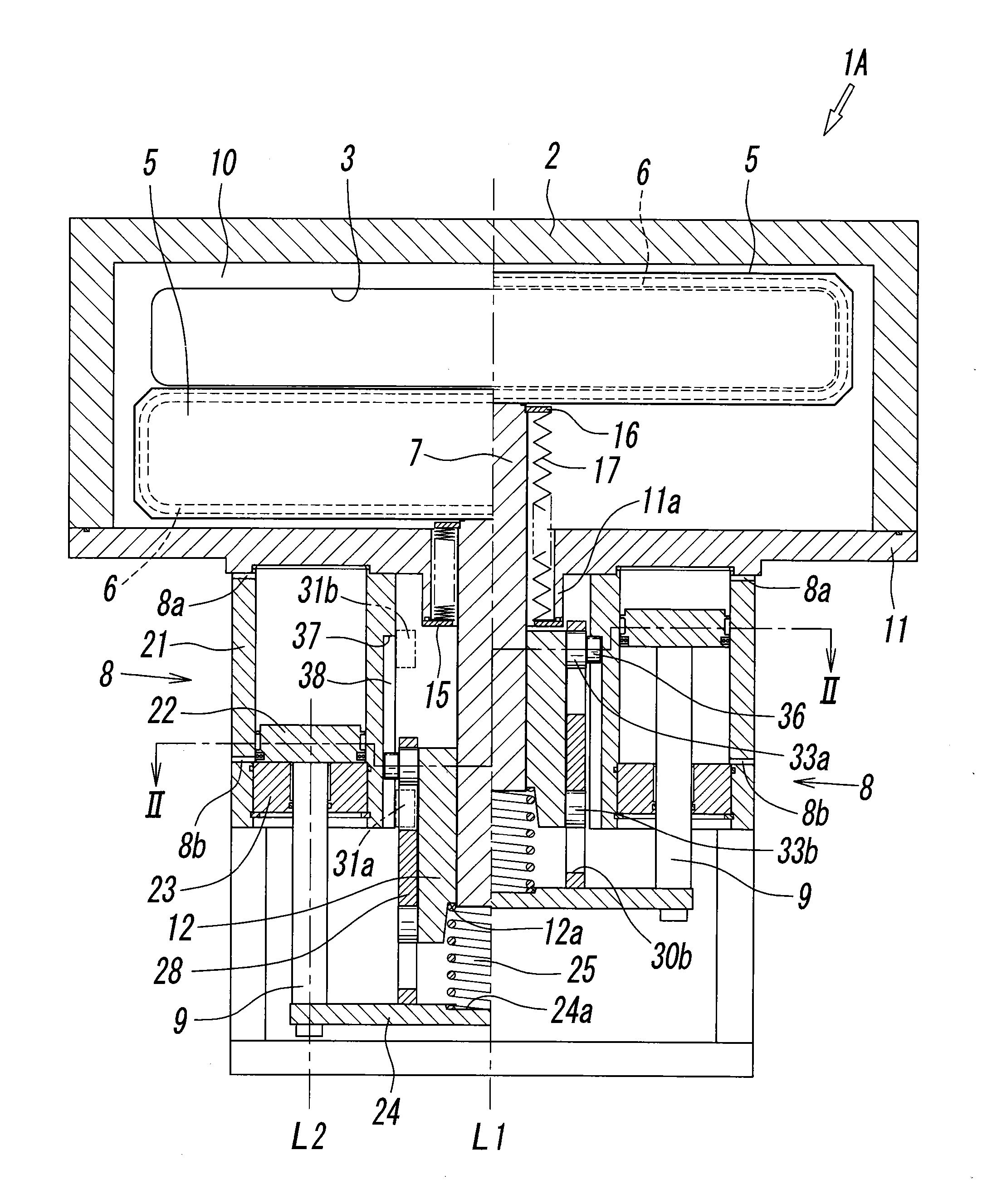
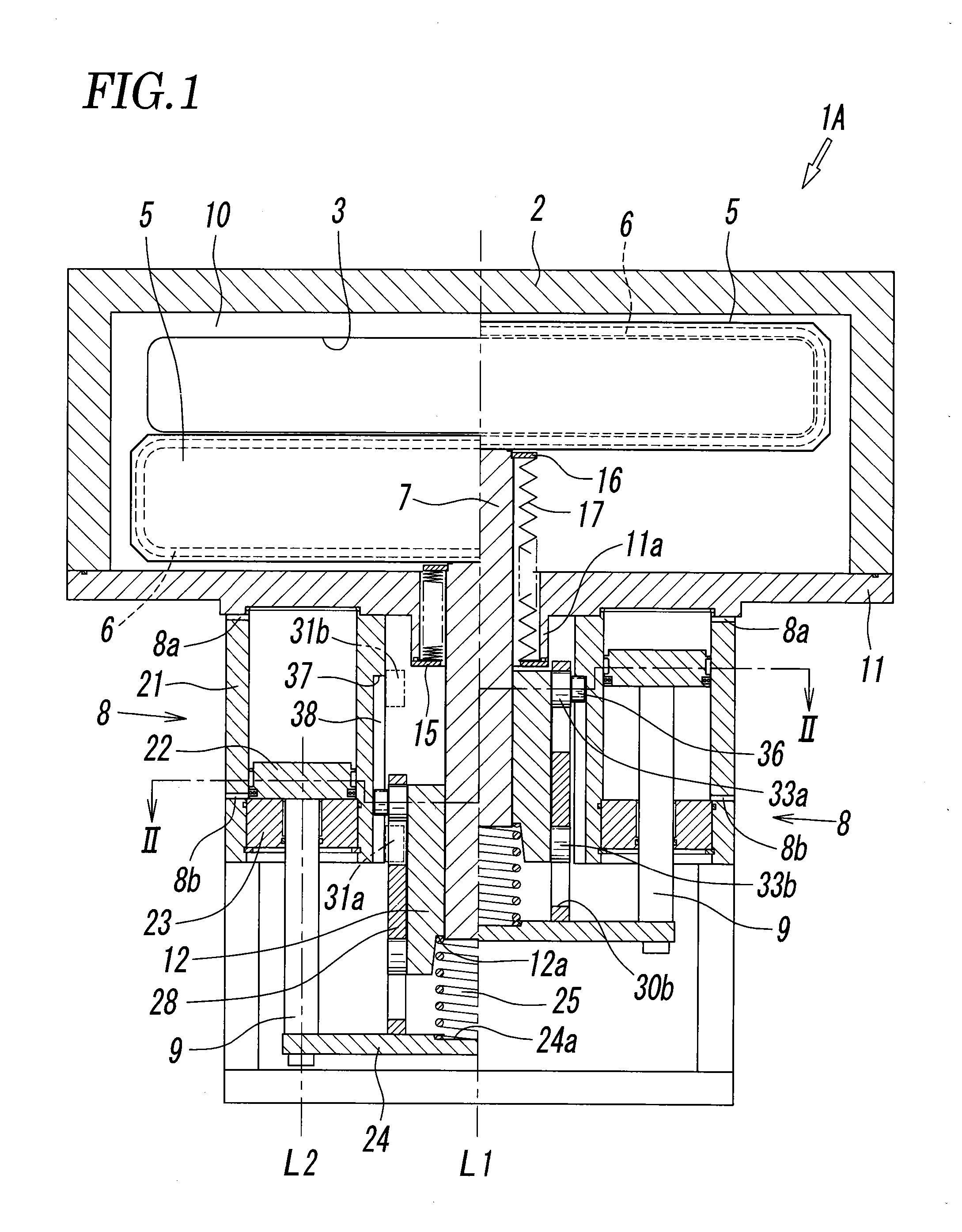
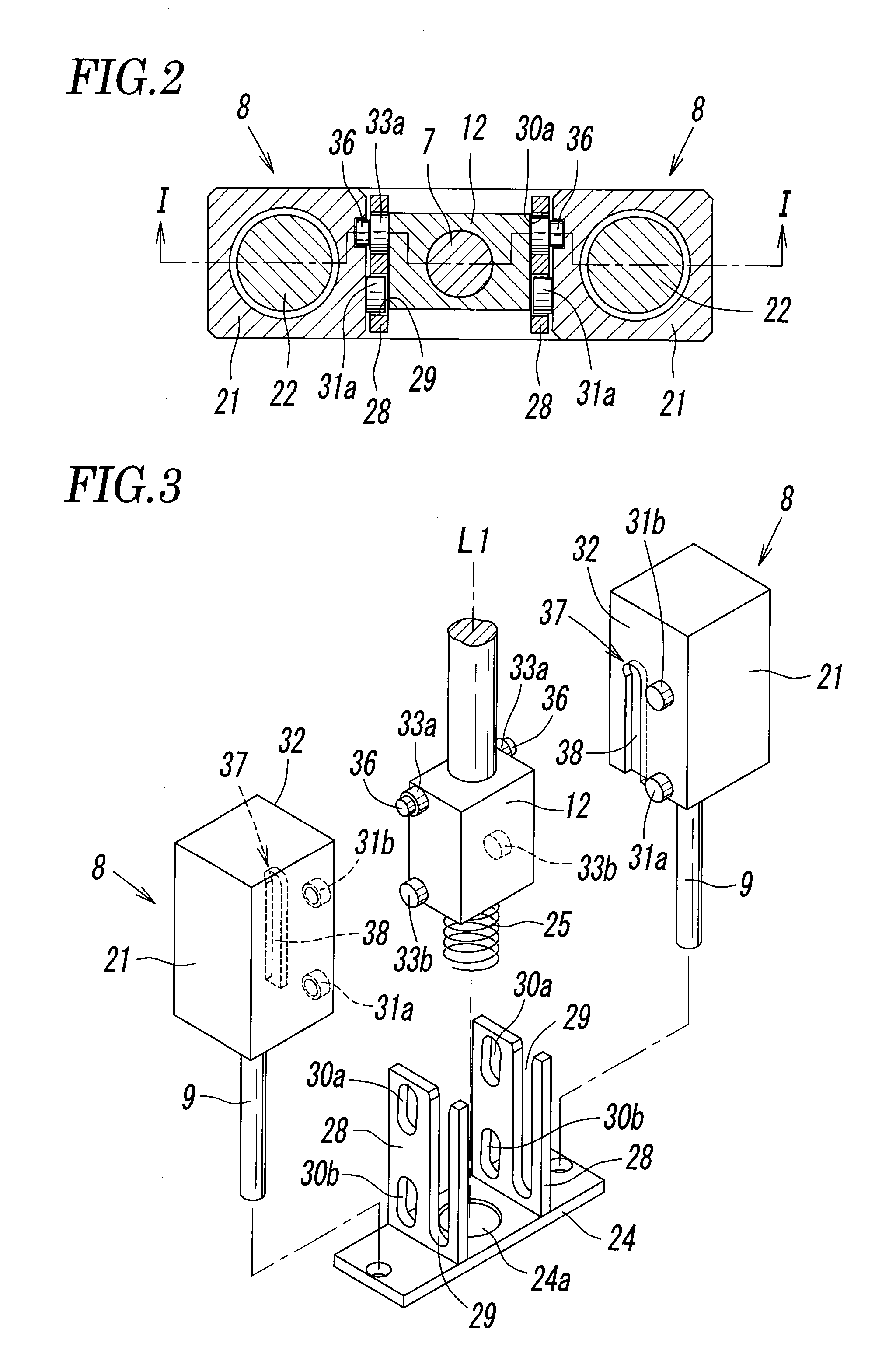
[0040]FIG. 1 to FIG. 8 shows a non-sliding gate valve according to the present invention. The gate valve 1A is mounted on a vacuum chamber in a semiconductor processing apparatus configured to open and close an opening communicating with the vacuum chamber, including a valve box 2 having the opening 3, a valve plate 5 housed in the valve box 2, a valve seal 6 mounted on the valve plate 5, a valve shaft 7 coupled to the valve plate 5, and an air cylinder 8 having a drive rod 9 coupled to the valve shaft 7, wherein the valve plate 5 takes a fully-opened position where the opening 3 is fully opened at a position not opposing the opening 3 (see the left half of FIG. 1 and FIG. 4), an opposing position where the valve plate 5 opposes the opening 3 but is not closed (see the right half of FIG. 1 and FIG. 5), and a closed position where the valve seal 6 is pressed against a valve seat surface 10 around the opening 3 and the opening 3 is closed (see FIG. 6 and FIG. 7) by moving the valve sh...

fourth embodiment

[0099]In contrast, in the case of the gate valve 1D of the fourth embodiment, the second cam roller 33b is located within the second groove portion 30d of the second cam groove 30b as illustrated in FIG. 18, and hence a force F2′ in the direction parallel to the valve seat surface 10 by the second cam groove 30b becomes F2′=(+W2)·(tan θ2). Here, since θ2>0, even when the relationship among W, W1, W2, D1 and D2 described above is the same as the case in FIG. 19, the force F2′ is larger than F2 in FIG. 19, and hence the value of the required thrust of the air cylinder Fc′=F1−F2′ becomes smaller than the value of Fc in FIG. 19.

[0100]Consequently, a compact air cylinder having a smaller thrust than the case of the first to third embodiments may be used as the air cylinder described above.

[0101]When the valve plate 5 is moved to the closed position and the back side of the valve plate 5 becomes the vacuum pressure P2 and the opening 3 side becomes the atmospheric pressure P1, there is a ...


PUM


Abstract

A parallel movement mechanism including guide grooves and guide rollers and a vertical movement mechanism including cam grooves and cam rollers are interposed between a drive rod and a valve shaft of an air cylinder, and a valve seal of a valve plate is moved vertically toward and away from a valve seat surface to open and close the opening by moving the valve shaft in parallel to the valve seat surface by the parallel movement mechanism and moving the same vertically with respect to the valve seat surface by the vertical movement mechanism.

Description

BACKGROUND OF THE INVENTION[0001]1. Field of the Invention[0002]The present invention relates to a gate valve mounted on a vacuum chamber in a semiconductor processing apparatus and used for opening and closing an opening communicating with the vacuum chamber and, more specifically to a non-sliding gate valve configured to be capable of opening and closing the opening without sliding.[0003]2. Description of the Related Art[0004]In a semiconductor processing apparatus, a gate valve is used for opening and closing an opening communicating with a vacuum chamber. The gate valve generally includes a valve plate configured to open and close the opening, a valve shaft coupled to the valve plate, and an air cylinder coupled to the valve shaft, and is configured to open and close the opening by bringing a valve seal of the valve plate toward and away from a valve seat surface around the opening by operating the valve shaft with the air cylinder.[0005]Examples of the gate valves include a sys...

Claims


Application Information

Patent Timeline
Patent Type & Authority Applications(United States)
IPC IPC(8): F16K3/16
CPCF16K3/16F16K3/3165F16K3/184F16K3/18F16K51/02H01L21/67
Inventor ISHIGAKI, TSUNEOSHIMODA, HIROMIOGAWA, HIROSHI
Owner SMC CORP
Why Eureka
Try Eureka