

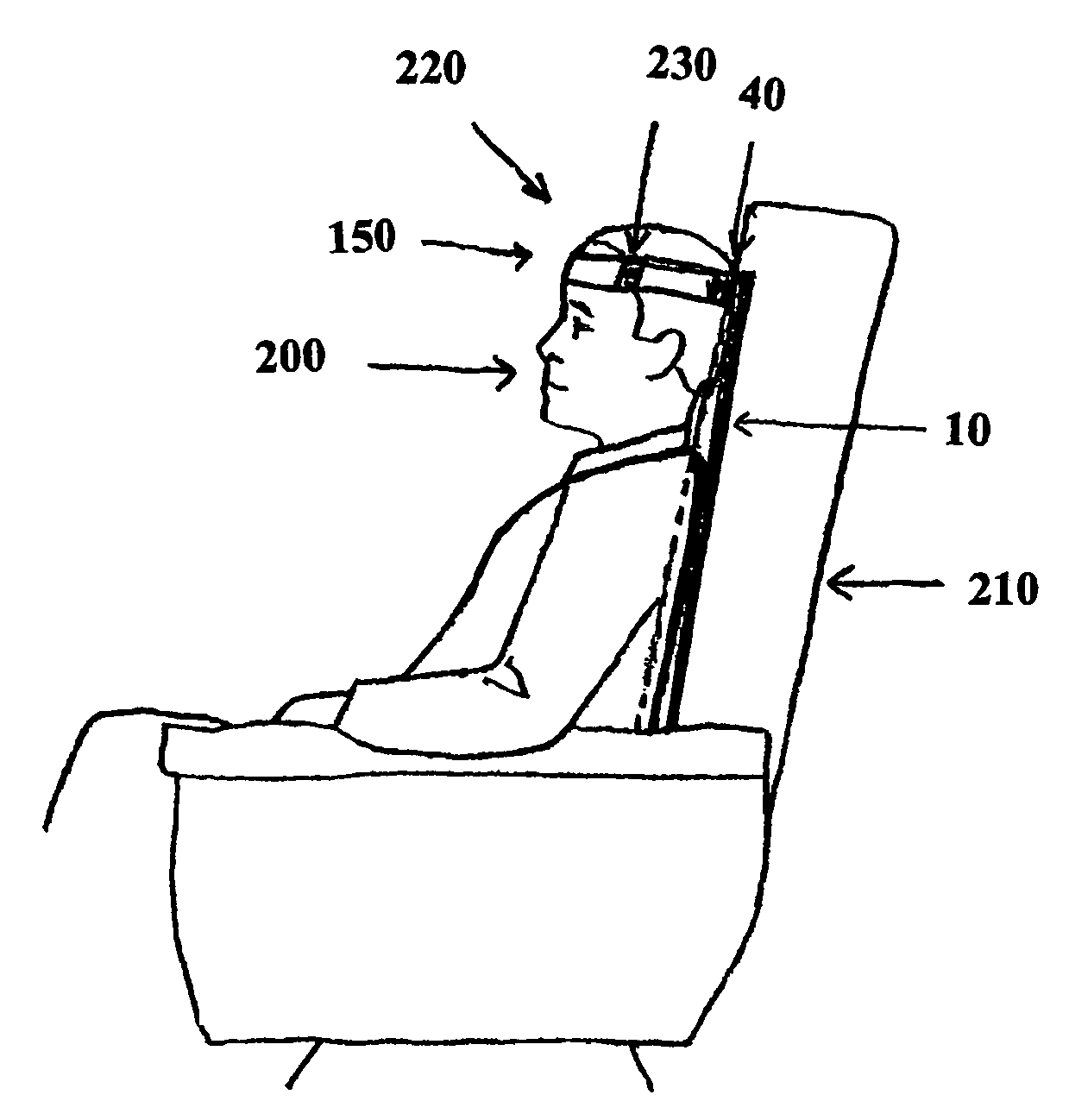
Device and method for head restraint
a head restraint and head support technology, applied in the field of head restraint devices and methods, can solve the problems of inconvenience for travelers, difficulty in obtaining adequate neck and head support, and pain for travelers, and achieve the effect of reducing snoring and other undesirable sleep related activities
- Summary
- Abstract
- Description
- Claims
- Application Information
AI Technical Summary
Benefits of technology
Problems solved by technology
Method used
Image

Examples
example 1
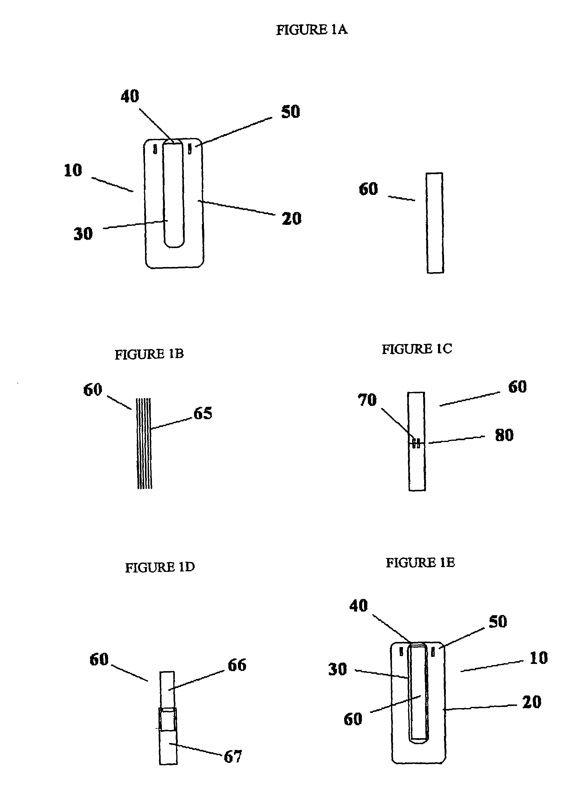
[0101]A rigid support comprising ⅛th inch thick acrylic was fabricated to be 4 inches wide and 16 inches long. The support was covered with two layers of 3 mm neoprene. The attachment apparatus was fabricated by gluing a 3-inch wide strip of neoprene to the back of the support at the upward portion to form a “belt-loop” structure. The securing apparatus was made by first cutting a strip of sailcloth approximately 2 inches wide and 24 inches long. Velcro was affixed to the ends. The strip was cut in half in the middle and a 2-inch piece of elastic was attached to connect the two pieces back together. A headpiece / eye mask was fabricated from fleece such that the strip of sailcloth could be threaded through the headpiece where it meets the user's forehead. The eye mask portion can be folded up or down when the device is in use.
[0102]The sailcloth was threaded through the “belt loop” on the back of the support device and the ends were attached by the Velcro such that the securing appara...
example 2
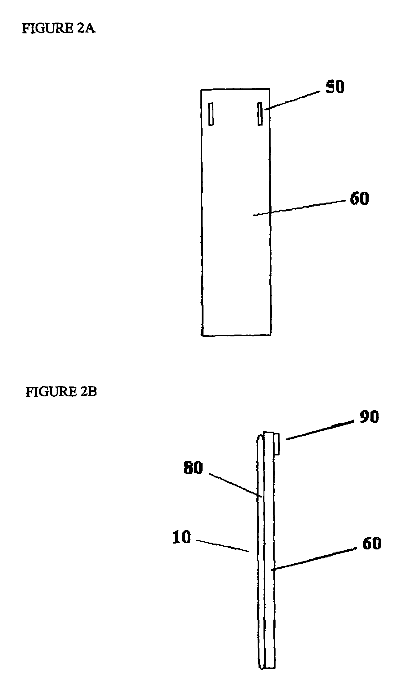
[0103]A rigid support consisting of ⅛th inch thick acrylic was fabricated to be 4 inches wide and 12 inches long. A support cover was fabricated of nylon and fleece with a pocket sized to fit the acrylic support. The support cover extended 4 inches below the bottom of the rigid support when the rigid support was placed in the support cover pocket. The attachment apparatus was fabricated by putting slots on either side of the top of the cover piece such that the securing apparatus could be threaded through the slots. The securing apparatus was made by first cutting a strip of sailcloth approximately 2 inches wide and 24 inches long. Velcro was affixed to the ends. The strip was cut in half in the middle and a 2-inch piece of elastic was attached to connect the two pieces back together. A headpiece / eye mask was fabricated from fleece such that the strip of sailcloth could be threaded through the headpiece where it meets the user's forehead. The eye mask portion can be folded up or dow...
example 3
[0105]A rigid support consisting of 4⅛th inch thick acrylic pieces was glued to a piece of neoprene approximately 8 inches wide. The pieces were spaced according to FIG. 11. A second piece of neoprene, identical in size to the first piece, was glued such that a sandwich was created with the rigid support disposed in between the two neoprene pieces. The attachment apparatus was fabricated by cutting slots through the neoprene near the top such that the securing apparatus could be threaded through the slots. The securing apparatus was made by first cutting a strip of sailcloth approximately 2 inches wide and 24 inches long. Velcro was affixed to the ends. The strip was cut in half in the middle and a 2-inch piece of elastic was attached to connect the two pieces back together. A headpiece / eye mask was fabricated from fleece such that the strip of sailcloth could be threaded through the headpiece where it meets the user's forehead. The eye mask portion can be folded up or down when the...
PUM
 Abstract
Description
Claims
Application Information