Power distribution panel with modular inserts

Inactive Publication Date: 2006-02-28
COMMSCOPE TECH LLC
View PDF12 Cites 52 Cited by
  • Summary
  • Abstract
  • Description
  • Claims
  • Application Information

AI Technical Summary

Benefits of technology

[0006]The present invention further relates to a module including the components and circuitry to distribute power to other devices. The module is adapted to be removably mount

Problems solved by technology

The compact nature of the panels may make it difficult to access the interior of a panel, for instance, for repairs or routine maintenance.
However, removal of a panel from a rack may result in the equipment within that rack being depowered during the repair or maintenance.
Re

Method used


Image

  • Power distribution panel with modular inserts
  • Power distribution panel with modular inserts
  • Power distribution panel with modular inserts

Examples


Embodiment Construction

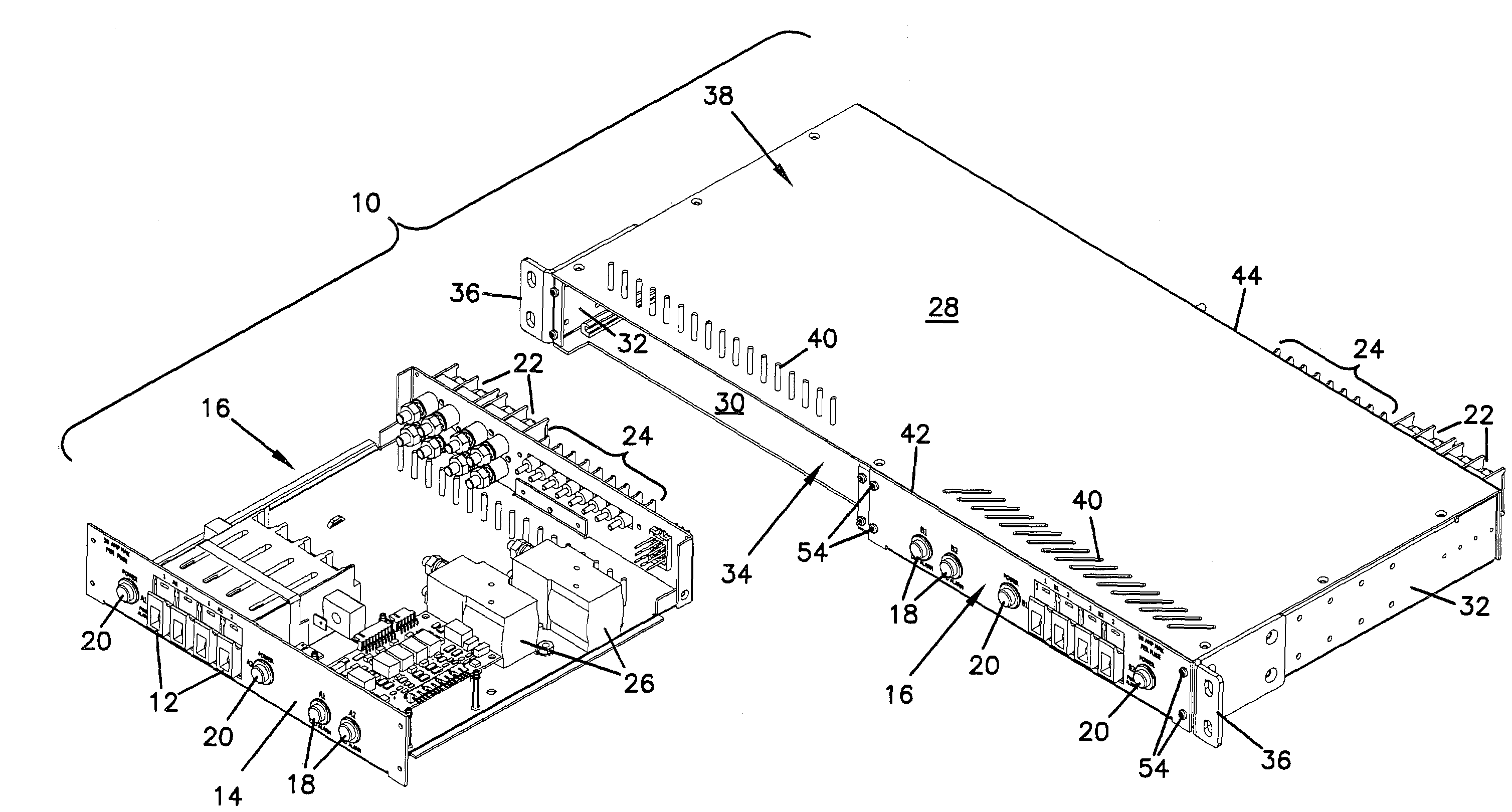
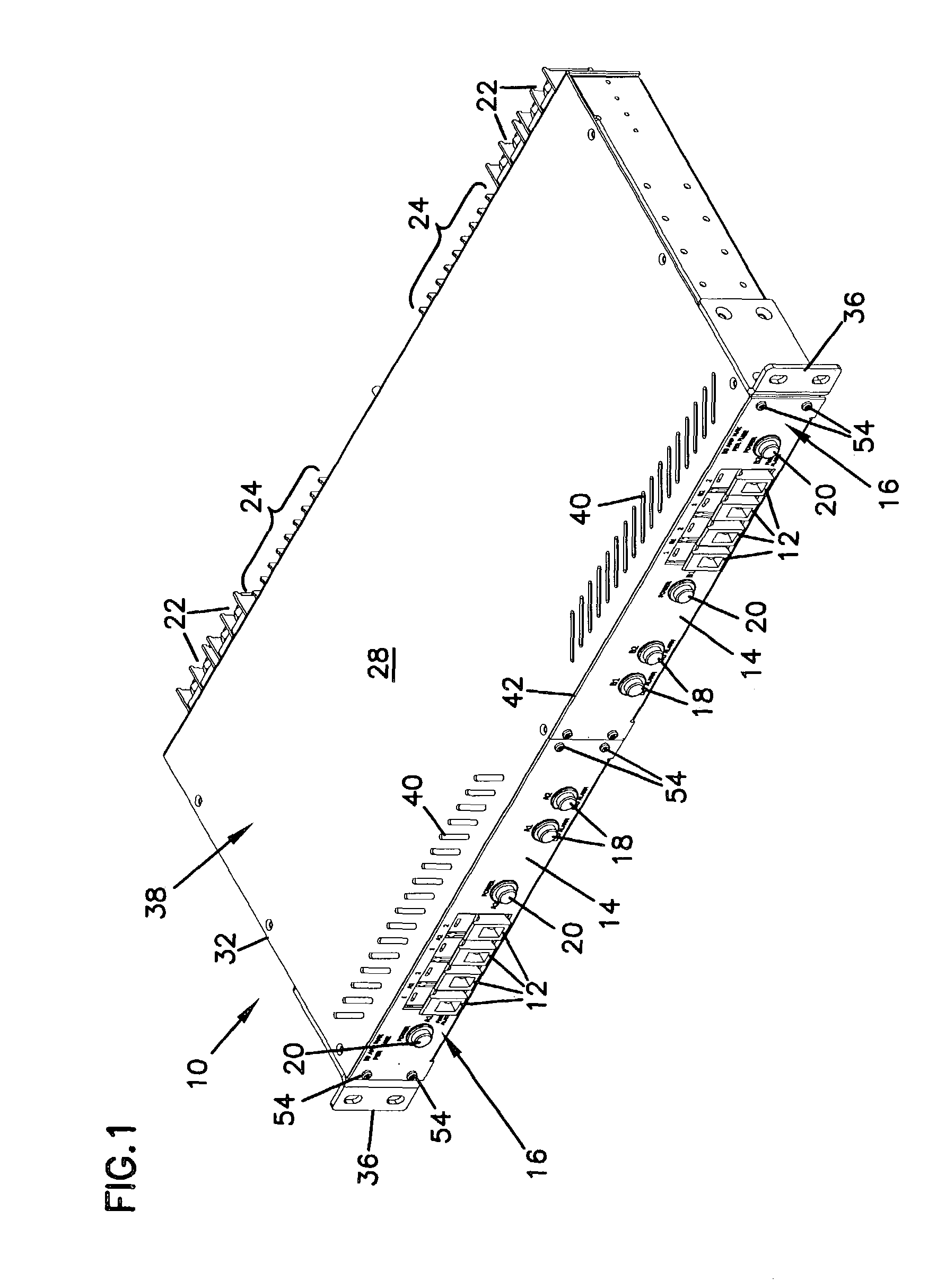
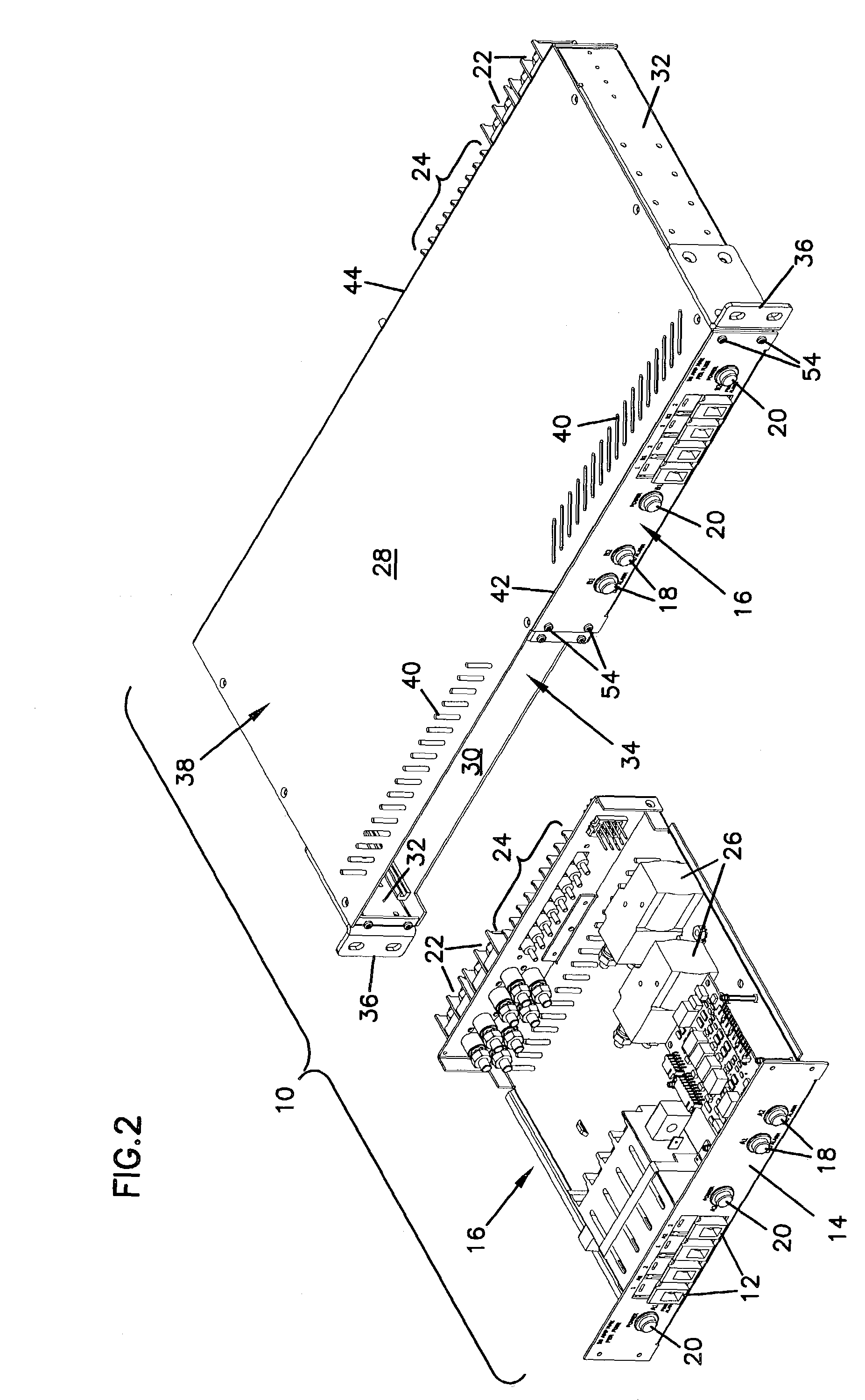
[0043]Reference now will be made in detail to exemplary aspects of the present invention that are illustrated in the accompanying drawings. Wherever possible, the same reference numbers will be used throughout the drawings to refer to the same or like parts.

[0044]Power distribution panels such as panel 10 shown in FIGS. 1 and 2 may be used to provide power for telecommunications or other electronic equipment mounted in equipment racks. The telecommunications or other electronic equipment is may be sensitive to fluctuations in the electrical power being supplied, and damaged by over-current or over-voltage conditions. Thus, panel 10 includes a plurality of circuit protection devices 12 mounted to a front face 14. Panel 10 includes two separate power busses, one in each of two modules 16 which on each side of panel 10. Each of the modules 16 shown in FIG. 1 has four circuit protection devices 12, which as shown are TPA fuses, each fuse 12 providing over-current and over-current protec...


PUM


Description

FIELD OF THE INVENTION[0001]The present invention relates generally to power distribution panels. More particularly, the present invention relates to power distribution panels with modular inserts.BACKGROUND OF THE INVENTION[0002]In telecommunication installations, equipment is often mounted in equipment racks. These racks permit greater density and organization of installation for this equipment. To simplify the provision of power to the equipment mounted within a rack, power distribution panels may be mounted in the same rack. These power distribution panels have one or more power input terminals to which higher capacity power supply cables may be attached. Within the panels is circuitry for distributing the current from the power input terminals to one or more power output terminals. From the output terminals, electrical cables may be led to the telecommunications equipment mounted within the rack. The circuits within the power distribution panel may also include circuit protecti...

Claims


Application Information

Patent Timeline
IPC IPC(8): G08B21/00H05K7/14H05K7/18
CPCH05K7/1457H05K7/186H05K7/1487
Inventor CABRERA, CARLOSHERNANDEZ, DELFINOJOHNSEN, DAVID J.
Owner COMMSCOPE TECH LLC
Why Eureka
Try Eureka