Aliasing communication system with multi-mode and multi-band functionality and embodiments thereof, such as the family radio service

a communication system and multi-mode and multi-band technology, applied in the field of receiver transmitter systems, can solve the problem of limited operation of conventional frs transceivers on a single frs channel

Inactive Publication Date: 2006-02-28
PARKER VISION INC
View PDF670 Cites 103 Cited by
  • Summary
  • Abstract
  • Description
  • Claims
  • Application Information

AI Technical Summary

Problems solved by technology

Generally, operation of a conventional FRS transceiver is limited to a single FRS channel.

Method used


Image

  • Aliasing communication system with multi-mode and multi-band functionality and embodiments thereof, such as the family radio service
  • Aliasing communication system with multi-mode and multi-band functionality and embodiments thereof, such as the family radio service
  • Aliasing communication system with multi-mode and multi-band functionality and embodiments thereof, such as the family radio service

Examples


Embodiment Construction

Overview of the Invention

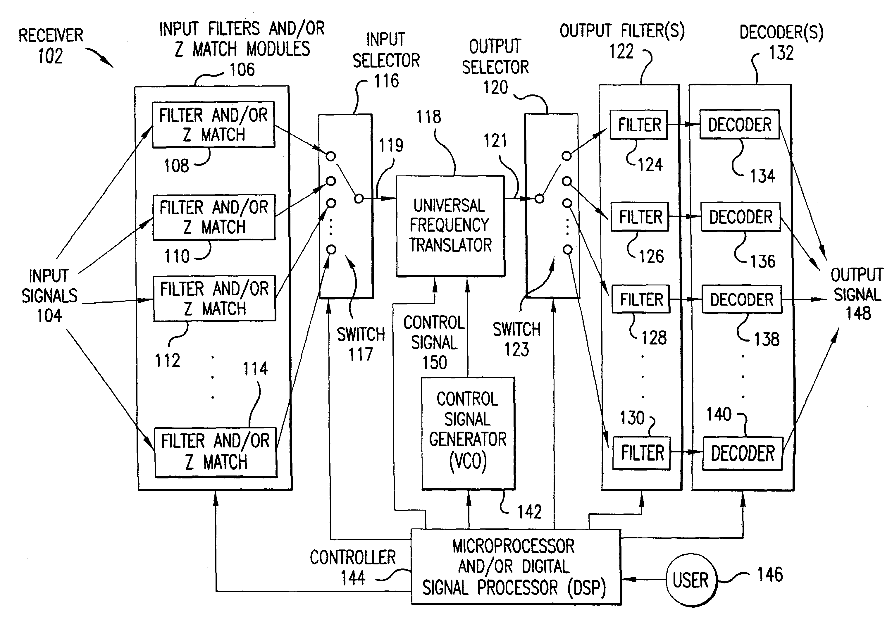
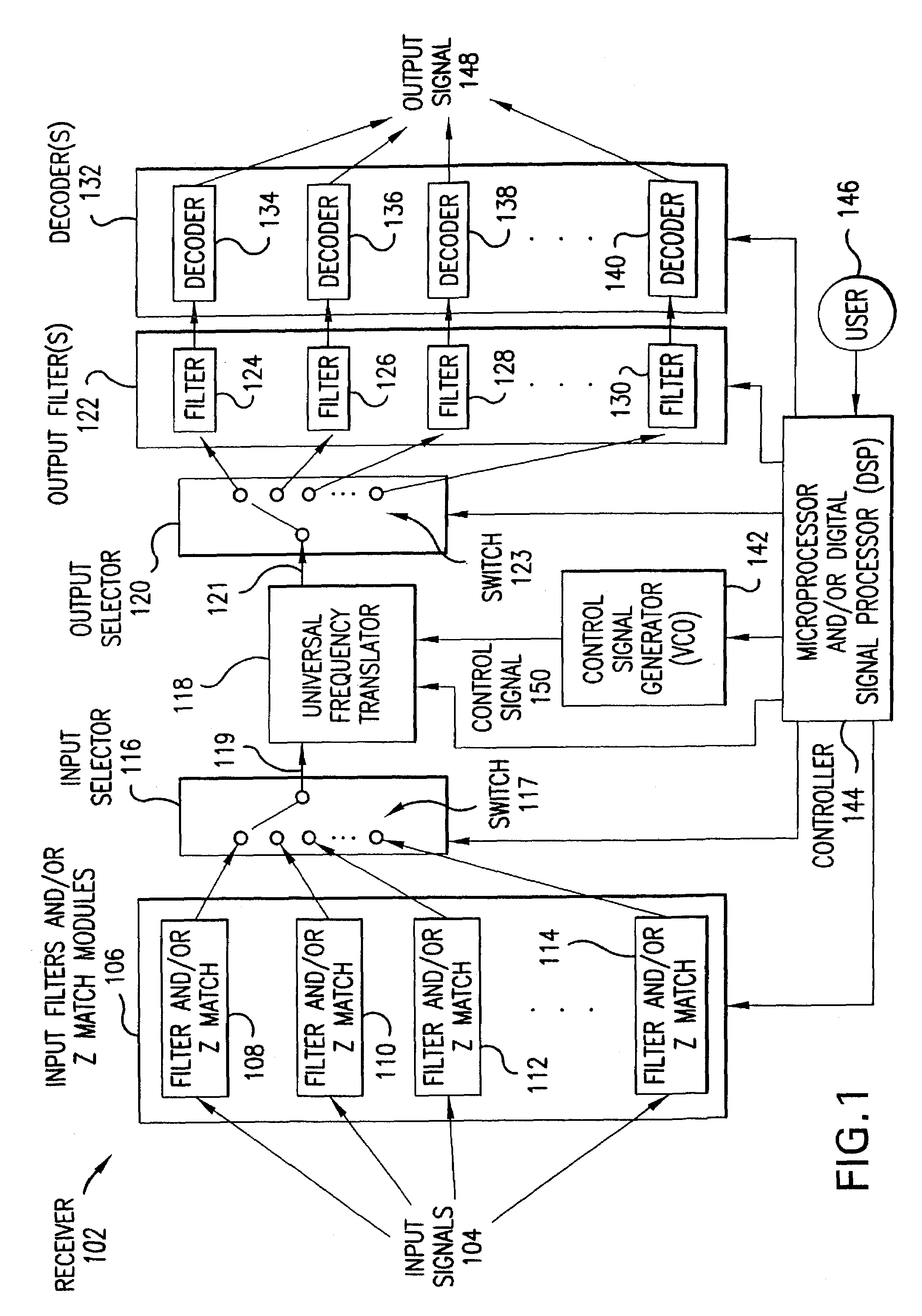
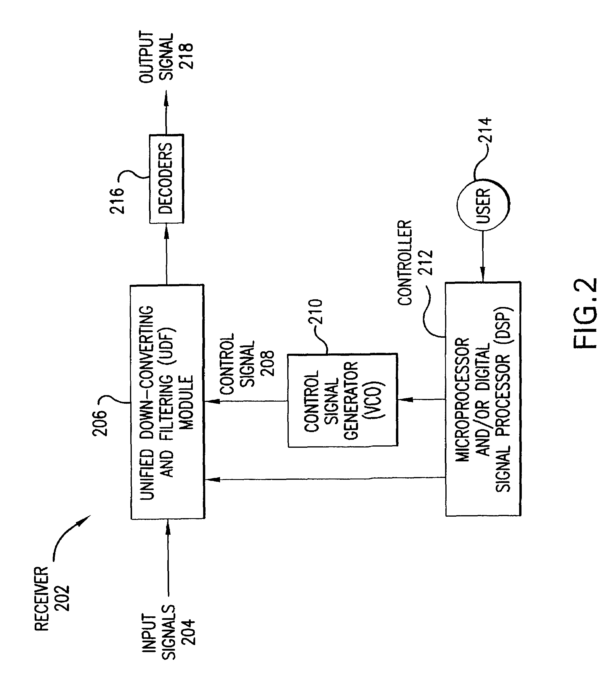
[0029]The invention is directed to a receiver having multi-mode and multi-band functionality and capabilities. According to the invention, the receiver is capable of selectively operating over a plurality of bands and channels. In an embodiment, the receiver operates in the following modes: (1) single band / channel mode; or (2) multiple band / channel mode.

[0030]In the single band / channel mode, the receiver is configured to receive information in a particular channel of a particular frequency band. The receiver may be dynamically reconfigured to listen to other channels and / or other bands.

[0031]In the multiple band / channel mode, the receiver is configured to receive information in one or more channels in one or more frequency bands. For example, and without limitation, the receiver could be configured to receive information from a plurality of channels of a single band, or one or more channels of a plurality of bands. A channel in a band that is being monitored...


PUM


Abstract

A receiver having multi-mode and multi-band functionality and capabilities is described herein. The receiver is capable of selectively operating over a plurality of bands and channels. The receiver operates in a plurality of modes, including but not limited to a single band/channel mode, and a multiple band/channel mode. The receiver may form a portion of a transceiver. The transceiver may also include a transmitter. In an embodiment, the transceiver is a family radio service (FRS) unit, although the invention is not limited to this embodiment.

Description

CROSS-REFERENCE TO OTHER APPLICATIONS[0001]This application claims the benefit of U.S. Provisional Application No. 60 / 116,847, filed Jan. 22, 1999, which is incorporated herein by reference in its entirety.[0002]The following applications of common assignee are related to the present application, and are incorporated herein by reference in their entireties:[0003]“Method and System for Down-Converting Electromagnetic Signals,” Ser. No. 09 / 176,022, filed on Oct. 21, 1998.[0004]“Method and System for Frequency Up-Conversion,” Ser. No. 09 / 176,154, filed on Oct. 21, 1998.[0005]“Method and System for Ensuring Reception of a Communications Signal,” Ser. No. 09 / 176,415, filed on Oct. 21, 1998.[0006]“Integrated Frequency Translation and Selectivity,” Ser. No. 09 / 175,966, filed on Oct. 21, 1998.[0007]“Image-Reject Down-Converter and Embodiments Thereof, Such as the Family Radio Service,” Serial No. 09 / 476,091, filed Jan. 3, 2000.[0008]“Analog Zero IF FM Decoder and Embodiments Thereof, Such a...

Claims


Application Information

Patent Timeline
Patent Type & Authority Patents(United States)
IPC IPC(8): H04B1/18
CPCH04B1/0057H04B1/406H04B1/0082H04B1/0075
Inventor SORRELLS, DAVID F.BULTMAN, MICHAEL J.CLEMENTS, CHARLES D.COOK, ROBERT W.HAMILLA, JOSEPH M.LOOKE, RICHARD C.MOSES, JR., CHARLEY D.SILVER, GREGORY S.
Owner PARKER VISION INC
Why Eureka
Try Eureka