Inhalation device

Inactive Publication Date: 2006-03-07
ASTRAZENECA AB
View PDF14 Cites 17 Cited by
  • Summary
  • Abstract
  • Description
  • Claims
  • Application Information

AI Technical Summary

Benefits of technology

[0005]By providing the nozzle block of the actuator with a tubular element over which the valve stem of a canister is located, medicament will deposit on the inner radial surface of the tubular element and not in the

Problems solved by technology

It will be appreciated that this deposition could lead to the user receiving an unusually high dose of medicament if the deposit were at least in part to break away or, indeed, result in the valve stems becoming blocked, the

Method used


Image

  • Inhalation device
  • Inhalation device
  • Inhalation device

Examples


Embodiment Construction

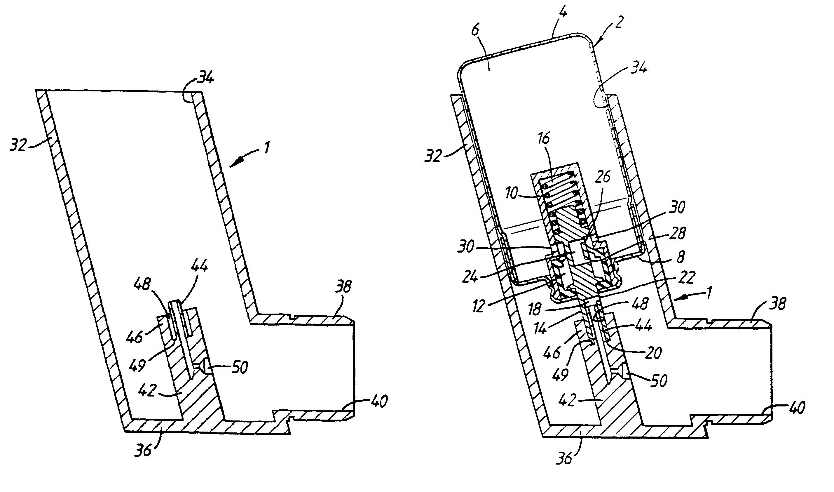
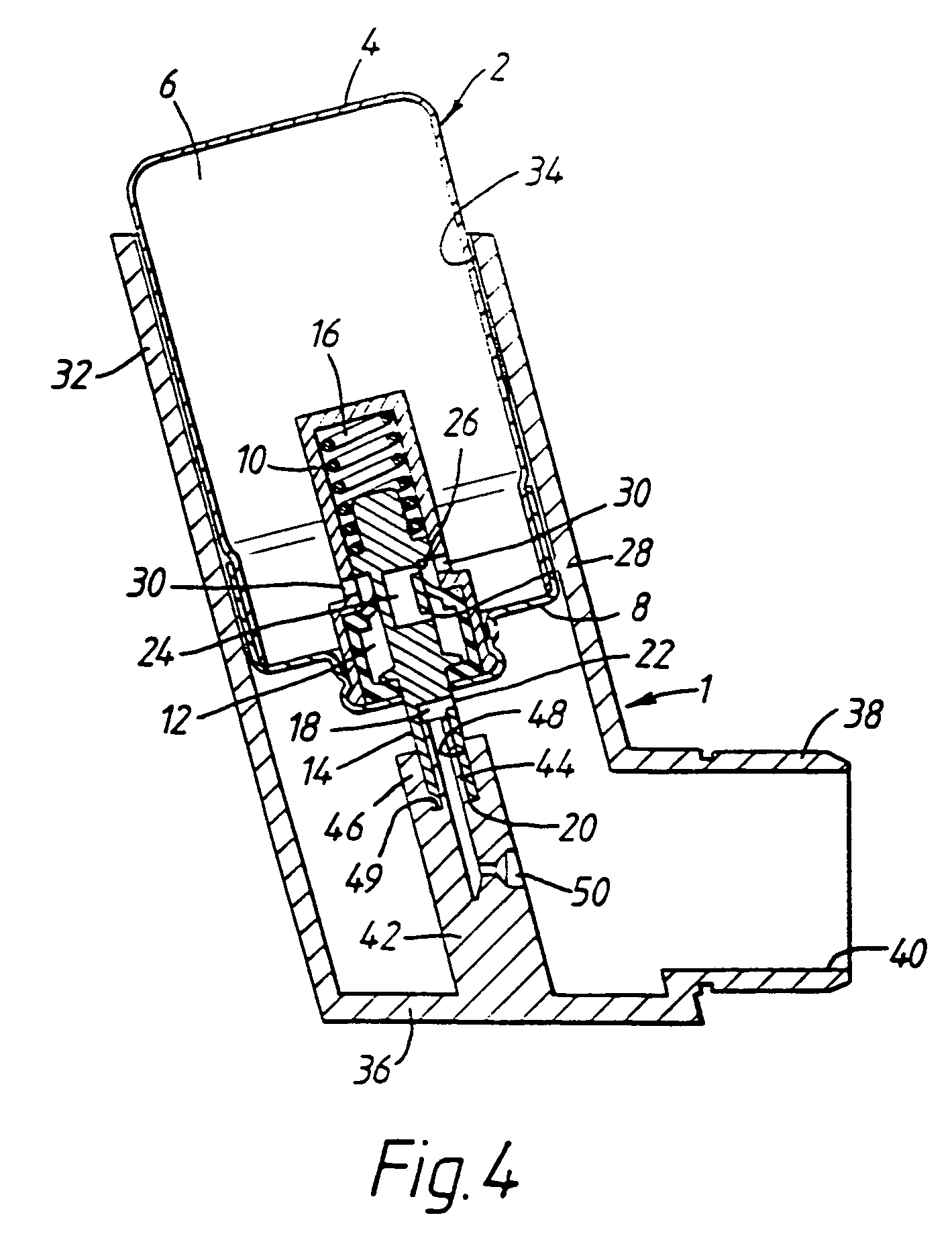
[0022]The canister 2 comprises a body 4 which defines a storage chamber 6 for holding a suspension or solution of a medicament in a propellant under pressure. The body 4 includes a head 8 which includes a housing 10 that defines a metering chamber 12 and a valve stem 14 that is movably disposed in the housing 10 and extends from the head 8. The valve stem 14 is movable between an extended, closed position (as illustrated) and a depressed, open position (not illustrated), the valve stem 14 normally being biased by a compression spring 16 disposed in the housing 10 into the closed position. The valve stem 14 includes a first conduit 18 which includes a first, outlet opening 20 located at the distal end of the valve stem 14 and a second, inlet opening 22 located in the side wall of the valve stem 14. The valve stem 14 further includes a second conduit 24 in that part thereof which is always disposed within the body 4. The second conduit 24 includes first and second axially-spaced openi...


PUM


Abstract

An actuator for a pressurised metered dose inhaler, including: a tubular section (38) providing an outlet through which medicament is in use inhaled; and a nozzle block (42) including a tubular element (44) having a free end over which the valve stem (14) of a canister (2) is in use located and a spray orifice (50) in fluid communication with the tubular element (44) for directing a spray into the tubular section (38).

Description

[0001]This application is a continuation of Application Ser. No. 09 / 840,875, filed Apr. 25, 2001, now abandoned which is a continuation of 09 / 380,294, filed Aug. 31, 1999, now abandoned, which is a National Phase under 35 U.S.C. §371 of PCT / SE99 / 01198, filed Jul. 3, 1999, the entire content of which is hereby incorporated by reference in this application.[0002]The present invention relates to an actuator for a pressurised metered dose inhaler and a pressurised metered dose inhaler including the same.BACKGROUND OF THE INVENTION[0003]In using conventional pressurised metered dose inhalers with some hydrofluoroalkane (HFA) formulations being developed by the applicant company it has been found that medicament tends to deposit in the valve stems of the canisters thereof. It will be appreciated that this deposition could lead to the user receiving an unusually high dose of medicament if the deposit were at least in part to break away or, indeed, result in the valve stems becoming blocked...

Claims


Application Information

Patent Timeline
IPC IPC(8): A61M11/00A61M15/00
CPCA61M15/009
Inventor BURNS, STEPHEN
Owner ASTRAZENECA AB
Why Eureka
Try Eureka