High endurance high capacity ball transfer unit

Active Publication Date: 2006-03-07
ROLLER BEARING OF AMERICA
View PDF25 Cites 46 Cited by
  • Summary
  • Abstract
  • Description
  • Claims
  • Application Information

AI Technical Summary

Problems solved by technology

As a result, most of the load on the conveyor ball is transferred to the housing adjacent the bottom of the well, and this is generally the weakest section for the housing.

Method used


Image

  • High endurance high capacity ball transfer unit
  • High endurance high capacity ball transfer unit
  • High endurance high capacity ball transfer unit

Examples


Embodiment Construction

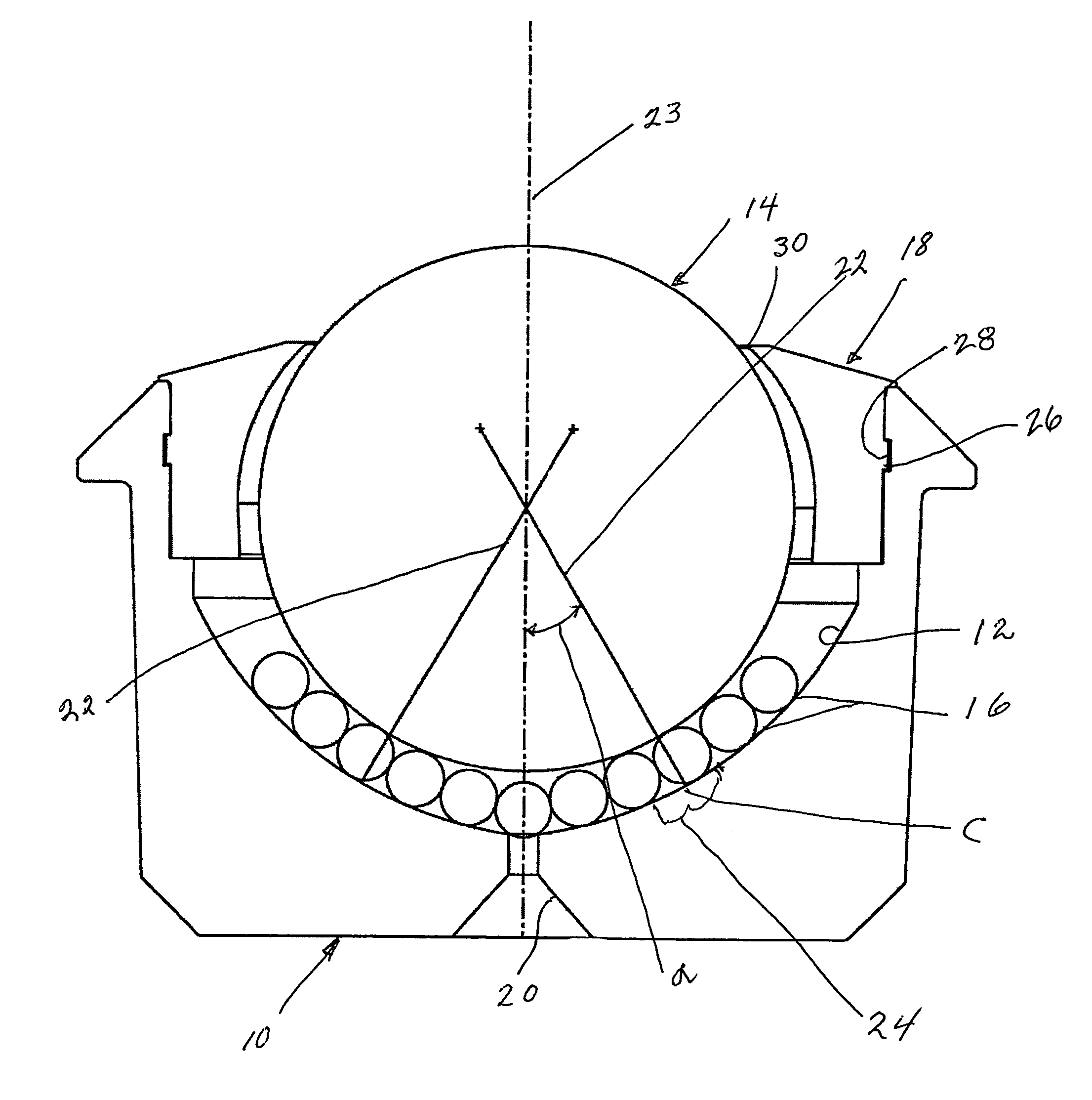
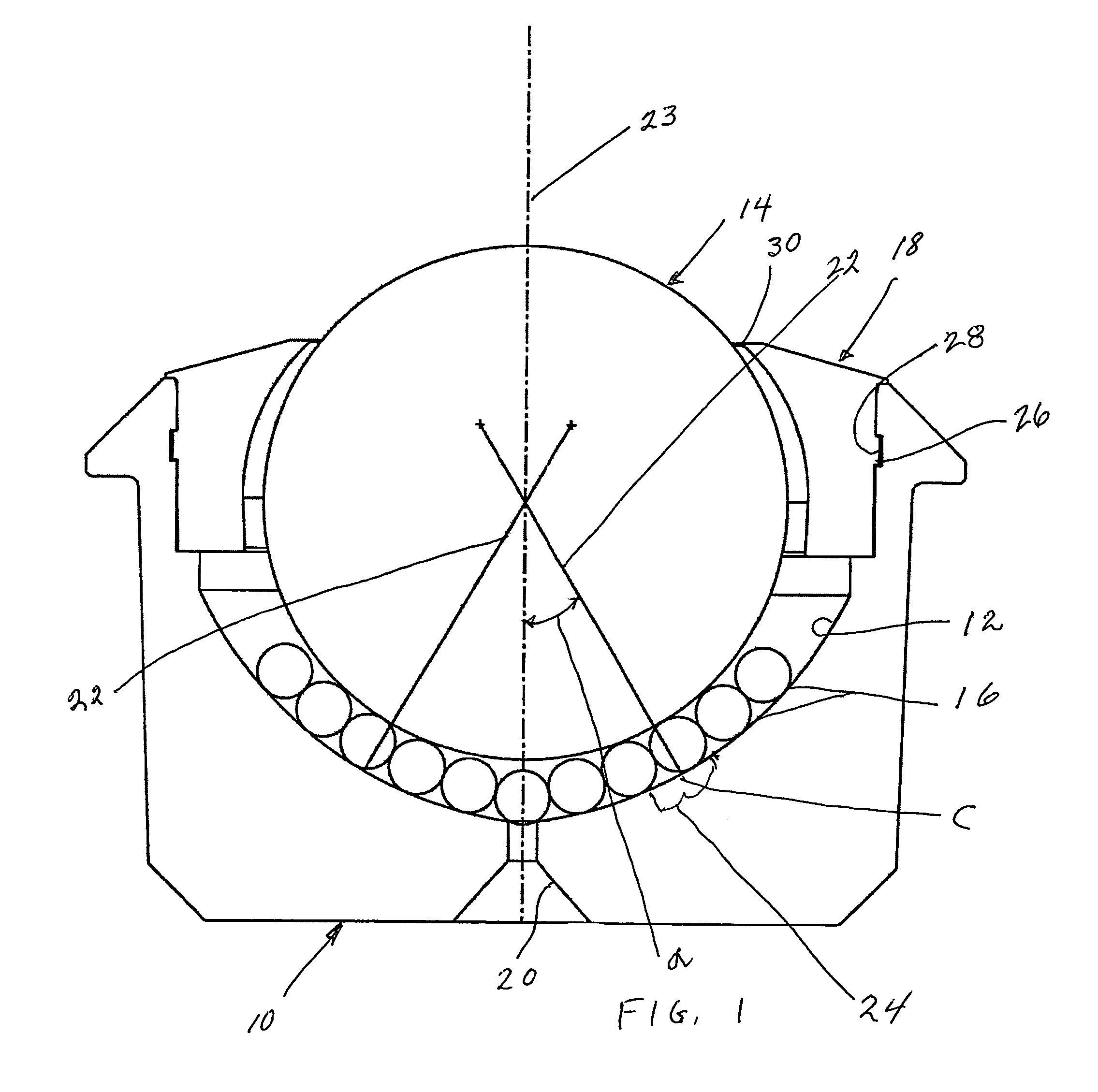
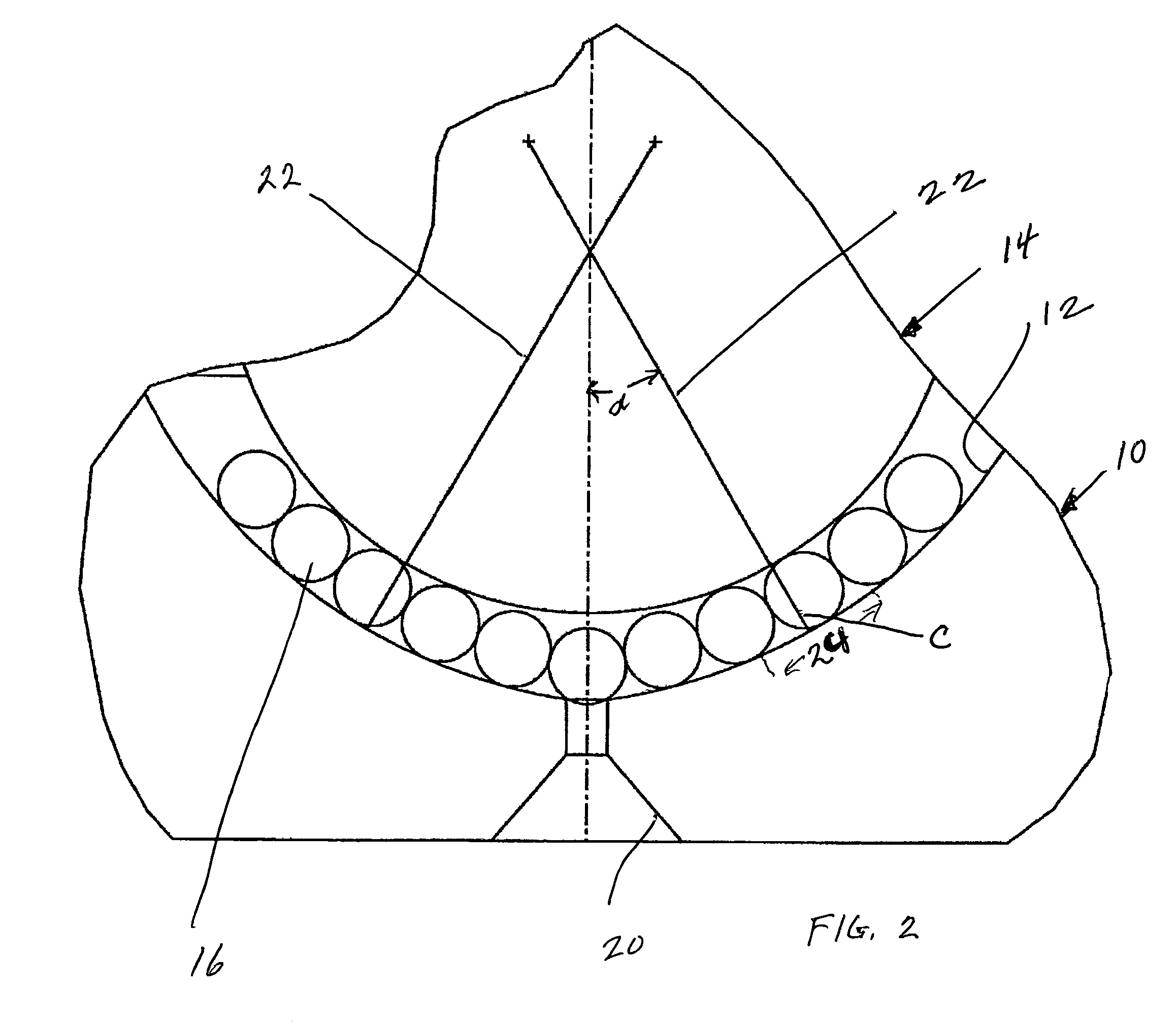
[0014]A ball transfer unit embodying the present invention has a housing generally designated by the numeral 10 with a cup-shaped well 12, a conveyor ball generally designated by the numeral 14, and a multiplicity of bearing balls 16 therebetween. A cap generally designated by the numeral 18 is seated in the upper portion of the well 12.

[0015]The outer surface of the housing 10 is of generally circular configuration and the well 12 and outer surface generate a generally annular cross section. The surface of the well 12 is provided with a corrosion-resistant electrodeposit such as zinc / nickel. At the lowest point of the well 12 there is a through passage 20 to discharge debris and water which may penetrate the seal provided by the cap 18.

[0016]The lower portion of the well 12 is not spheroidal but is generated by a pair of equal length radii 22 which are mutually offset from the vertical axis 23 and intersect at point A which is above the center B of the conveyor ball 14. The resulta...


PUM


Abstract

An extended life ball transfer unit has a housing with a well of generally cup-shaped configuration with at least the lower portion of its surface being defined by a pair of radii mutually offset to opposite sides from its vertical axis to generate a gothic church arch cross section. A passage extends therethrough at the base of the housing well. Sealed in the well is a spherical conveyor ball having a radius of smaller length than the radii defining the lower surface of the well, and the well defining radii having their origins above the center of the conveyor ball. A multiplicity of spherical bearing balls is disposed between the conveyor ball and at least the lower portion of the well. The bearing balls support the conveyor ball and transferring the load from the conveyor ball to the housing over an annular area defined by an arc of about 5-15° with its center spaced about 30°–40° upwardly from the passage. A annular cap is seated in the upper portion of the well and has an inner surface portion bearing against the surface of the conveyor ball to provide a sealing action limiting debris from passing into the lower portion of the well.

Description

BACKGROUND OF THE INVENTION[0001]The present invention relates to ball transfer units utilized to provide a conveying surface on which articles may be readily moved.[0002]Ball transfer units are widely employed in connection with conveyors for movement of various articles such as cargo from an aircraft. The ball transfer units are assembled in a housing or support to provide a surface containing many spherical balls upon which the articles are readily moved. Illustrative of such ball transfer units are Coelln U.S. Pat. No. 5,540,314, Barnes et al U.S. Pat. No. 5,516,211 and Huber U.S. Pat. No. 5,033,601.[0003]Generally, such ball transfer units comprise a housing providing a well in which a large conveyor ball is seated and the conveyor ball rides upon small ball bearings which in turn roll upon the surface of the well. Many units include caps to provide some sealing action at the upper portion of the well so as to limit debris from falling into the well and interfering with the ope...

Claims


Application Information

Patent Timeline
Patent Type & Authority Patents(United States)
IPC IPC(8): B65G13/00
CPCF16C29/046B65G39/025F16C2326/58
Inventor PALLINI, ROBERT A.SULLIVAN, KEVINGUILFORD, WERNER B.
Owner ROLLER BEARING OF AMERICA
Why Eureka
Try Eureka