Side contact rocker-type switch assembly

a technology of side contact and rocker switch, which is applied in the direction of tumbler/rocker switch details, contact mechanisms, electrical apparatus, etc., can solve the problems of cumbersome and inefficient assembly of the center contact area, and achieve the effect of less cumbersome assembly and less costly manufacturing

Inactive Publication Date: 2006-03-07
RELIANCE CONTROLS
View PDF19 Cites 13 Cited by
  • Summary
  • Abstract
  • Description
  • Claims
  • Application Information

AI Technical Summary

Benefits of technology

[0008]It is an object of the present invention to provide an improved rocker-type switch assembly with a simplified design that is less cumbersome to manufacture, and yet functions in an effective manner to selectively connect a power supply between separate electrical loads, or selectively connect an electrical load between separate power supplies.
[0012]The improved electrical switch assembly eliminates the center contact disposed in the housing, such that the switch assembly is less cumbersome to assemble and less costly to manufacture.

Problems solved by technology

Furthermore, the configuration of the center contact area is cumbersome and inefficient to assemble.

Method used


Image

  • Side contact rocker-type switch assembly
  • Side contact rocker-type switch assembly
  • Side contact rocker-type switch assembly

Examples


Embodiment Construction

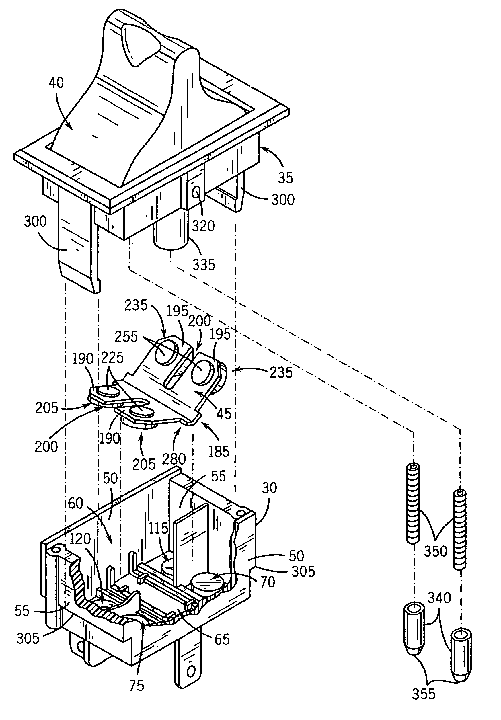
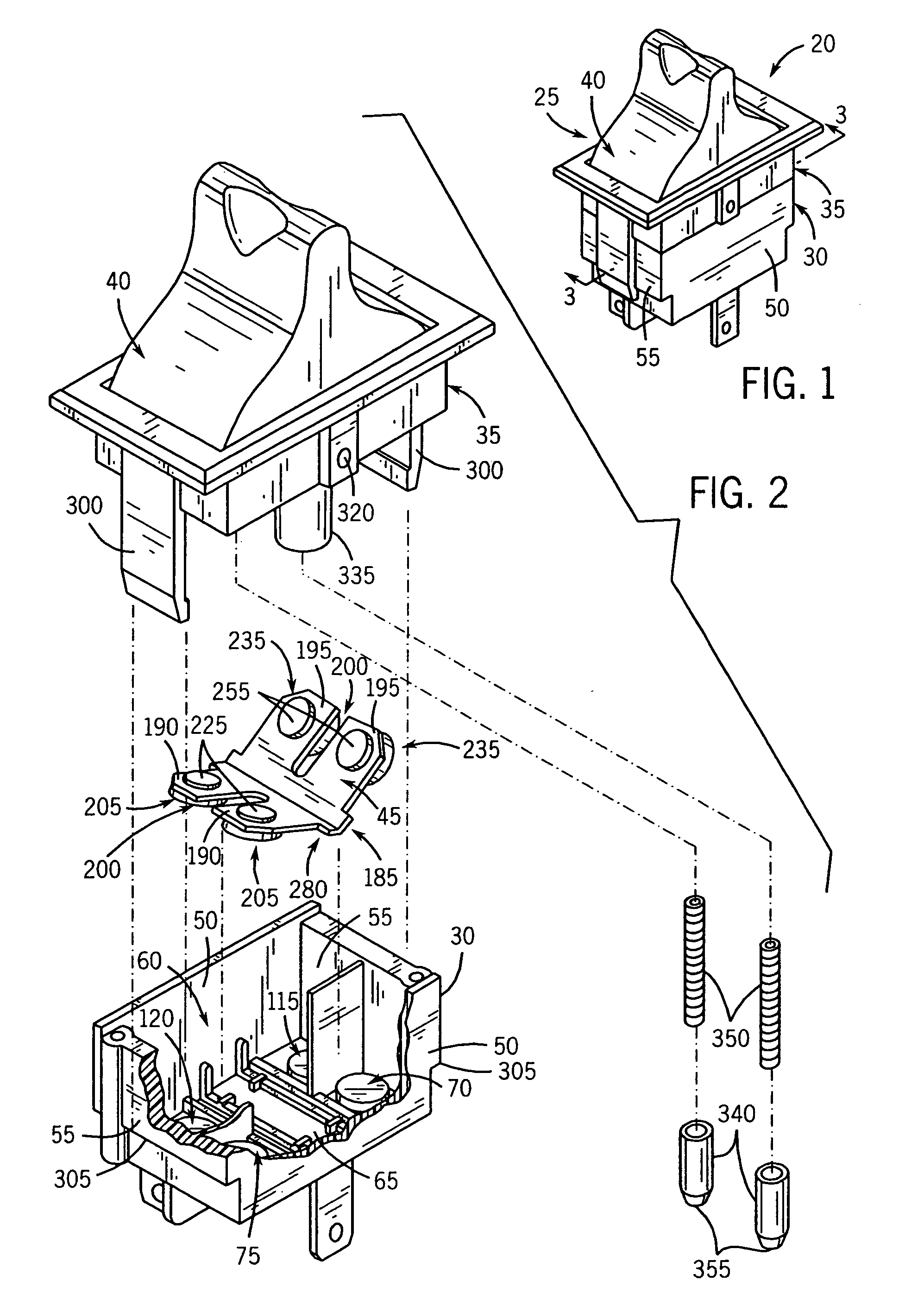
[0028]Referring to FIGS. 1 and 2, an electrical switch assembly 20 of the present invention generally includes a housing 25 made up of a base 30, a cover 35, and an actuator 40. The actuator 40 controls movement of a movable contact member 45 positioned within the housing 25.

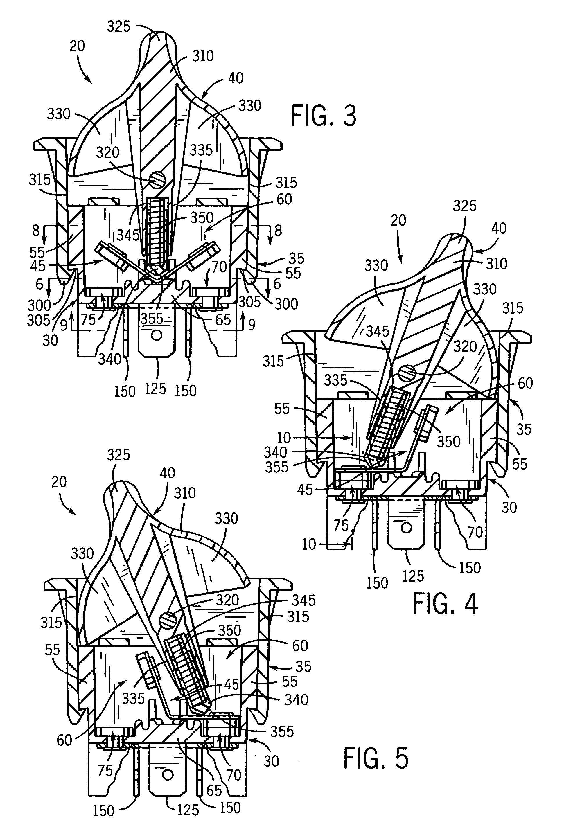
[0029]Referring to FIGS. 1–6, the housing base 30 includes a pair of side walls 50 and a pair of end walls 55, which cooperate to define an internal cavity 60 within which the movable contact member 45 is received. The side walls 50 and the end walls 55 extend upwardly from a bottom wall 65, which defines the lower extent of the internal cavity 60.

[0030]Referring to FIGS. 2, 6 and 10, a series of stationary contacts are secured to the bottom wall 65 of the housing base 30. The stationary contacts include a first contact 70 and a second contact 75. As illustrated in FIG. 10, each stationary contact 70 (not shown) and 75 includes a contact head 85 defining an upwardly facing contact surface 90, in combination with...


PUM


Abstract

An electrical switch assembly is provided for use as a single-pole, double-throw switch. The assembly includes a housing having an interior cavity. First and second stationary contacts are positioned on one side of the interior cavity, and third and fourth stationary contacts are positioned on the other side of the interior cavity. A conductive member is interconnected between the first and third stationary contacts. A movable contact member is configured in one operative position to complete an electrical path between the first and the second stationary contacts, configured in a second operative position to complete an electrical path between the third and the fourth stationary contacts, and configured in an inoperative or OFF position to be electrically disconnected from all four stationary contacts. The improved switch assembly eliminates a center contact disposed in the housing, such that the switch assembly is less cumbersome and costly to manufacture and assemble.

Description

BACKGROUND AND SUMMARY OF THE INVENTION[0001]This invention relates to an electrical switch assembly such as a single-pole, double-throw electrical switch, and more particularly to an improved construction of a rocker type switch assembly configured without a center contact.[0002]A known rocker-type electrical switch assembly, such as a single pole double throw (SPDT) switch assembly, typically includes a housing having first and second stationary contacts mounted on opposite sides of an interior cavity. A stationary “center” contact is centrally located between the stationary first and second contacts. In the prior art, the center contact is channel-shaped and interconnected with a prong that extends from the bottom portion of the housing.[0003]A V-shaped movable contact member or rocker formed of an electrically conductive material is engaged with and pivotable about the channel-shaped center contact. The V-shaped movable contact member includes a first leg and a second leg that a...

Claims


Application Information

Patent Timeline
Patent Type & Authority Patents(United States)
IPC IPC(8): H01H3/00
CPCH01H23/205H01H23/08
Inventor CZARNECKI, NEIL A.FLEGEL, DAVID D.
Owner RELIANCE CONTROLS
Why Eureka
Try Eureka