Drywall cornerbead with paper legs

a paper leg and corner bead technology, which is applied in the field of paper leg corner bead improvement, can solve the problems of paper being easily scuffed or torn with only minimal contact, and affecting the appearance of the bead

Active Publication Date: 2006-03-21
PHILLIPS MFG
View PDF6 Cites 24 Cited by
  • Summary
  • Abstract
  • Description
  • Claims
  • Application Information

AI Technical Summary

Problems solved by technology

However, one problem associated with such “paper bead” is the scuffing and damage to the paper covering the curved nose of the bead once the bead has been installed on a corner.
Because the curved nose portion of the bead is directly exposed, and has no plaster or other material covering the paper, the paper may be easily scuffed or torn with only minimal contact.
While this assembly apparently works sufficiently for its intended purpose, it also suffers drawbacks.
The cost to manufacture the product is greater than necessary because of the use of two layers of flexible material, such as paper.
Second, this cost is increased by virtue of the fact that the front and rear layers must be accurately positioned in order to provide the desired overlap, so that the layers can be adhered to each other (in yet an additional manufacturing step) in the area where they protrude beyond the terminal edges of the flanges.
Thus, cost of material is high, and time required for manufacturing is high.

Method used


Image

  • Drywall cornerbead with paper legs
  • Drywall cornerbead with paper legs
  • Drywall cornerbead with paper legs

Examples


Embodiment Construction

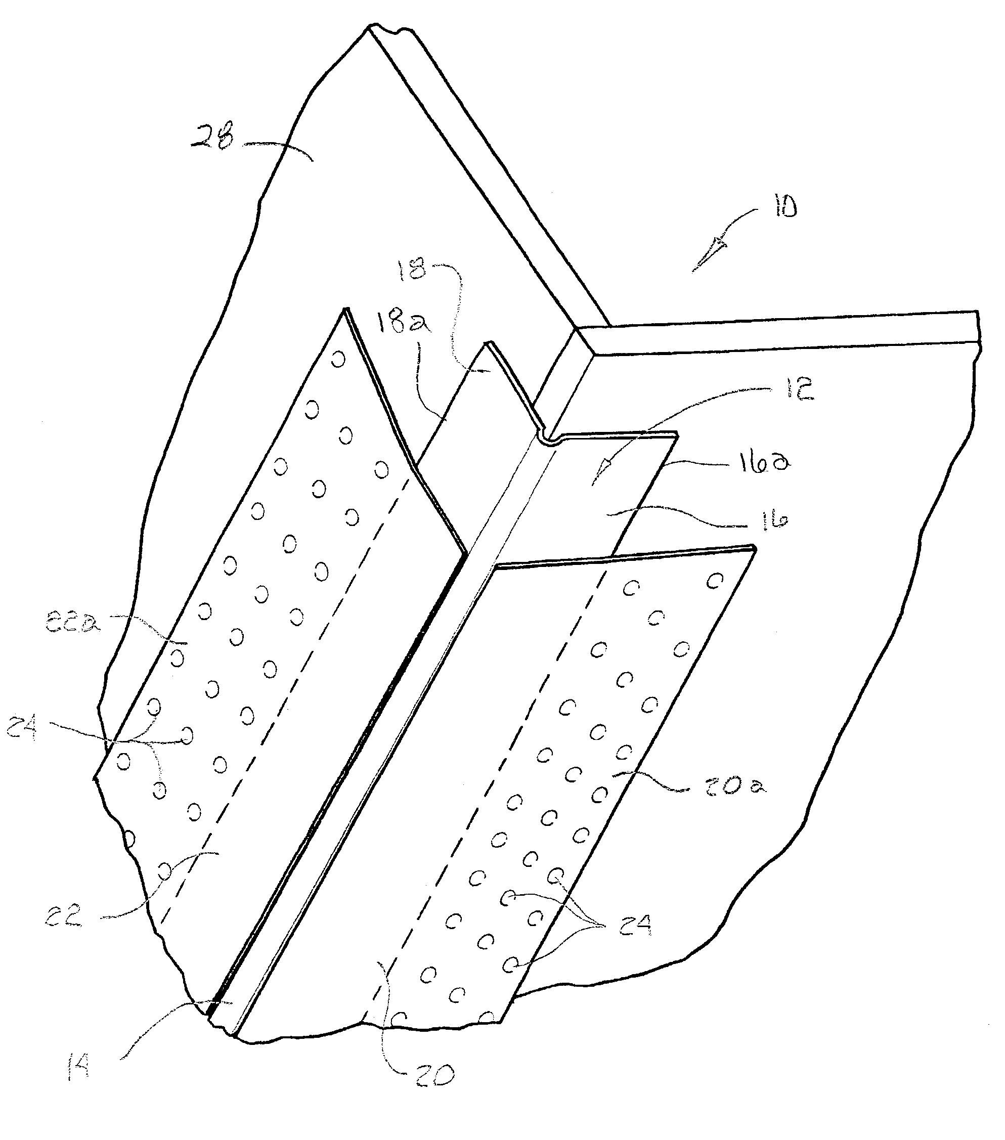
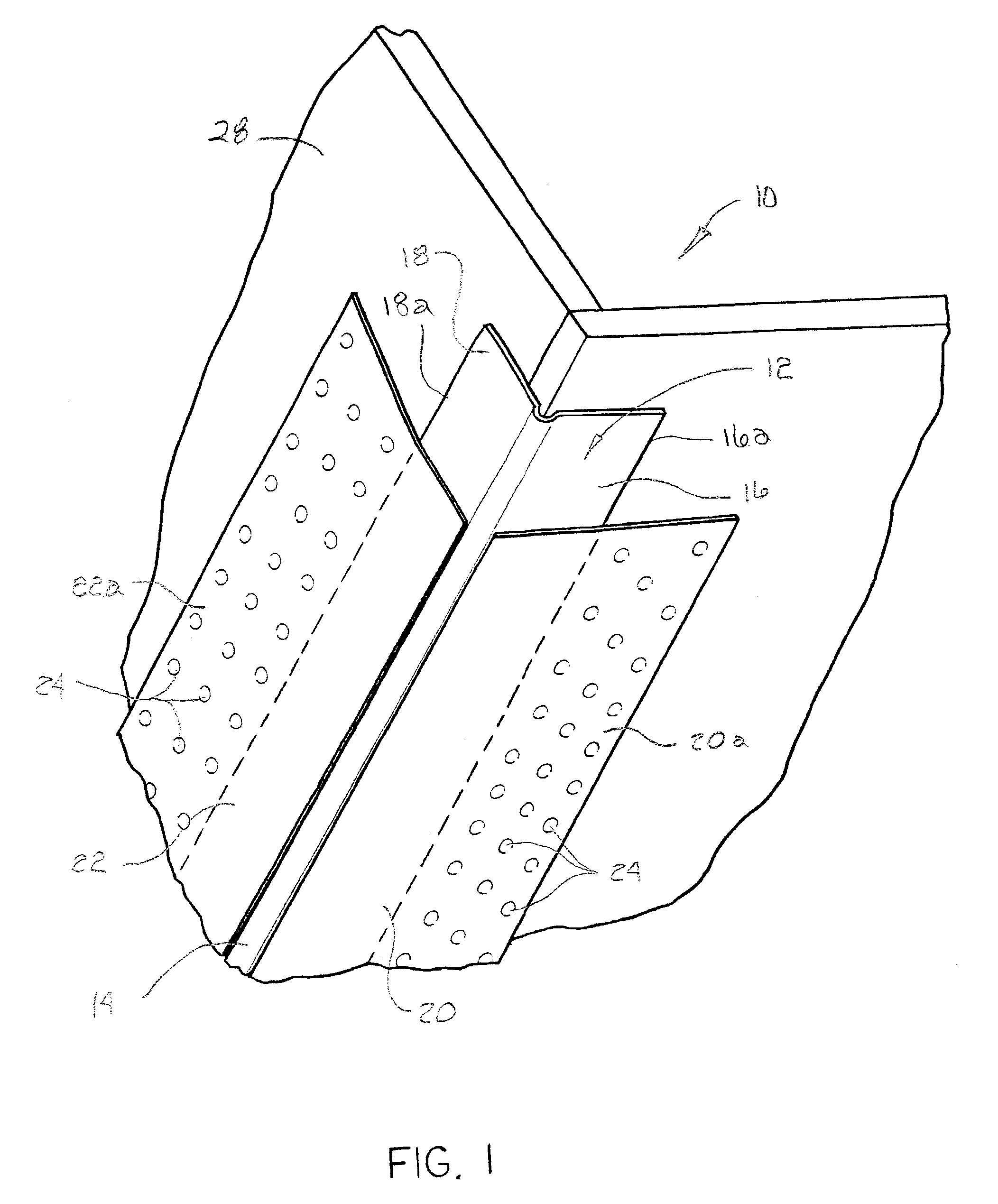
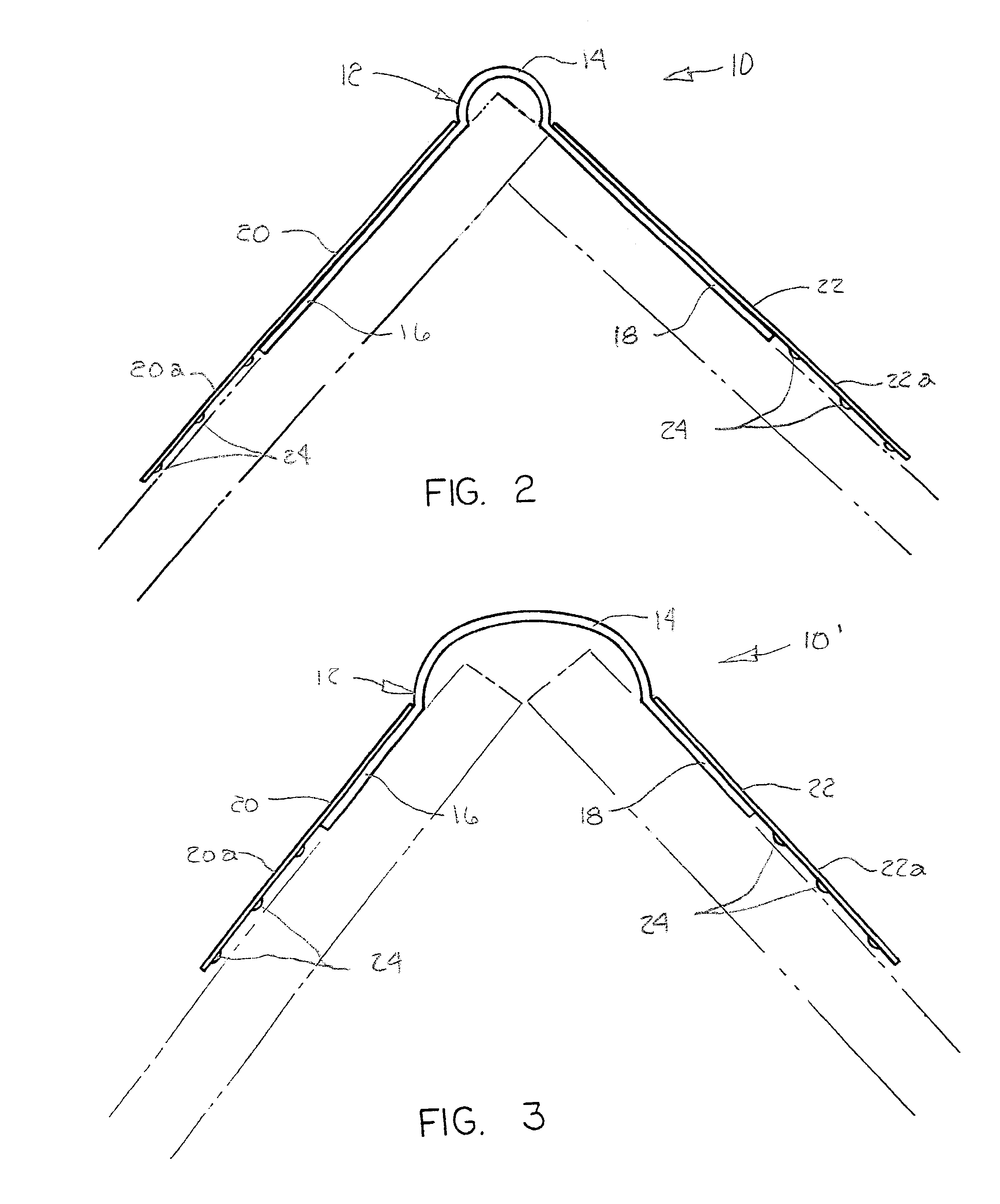
[0020]Referring now to the drawings, in which similar or corresponding parts are identified with the same reference numeral, and more particularly to FIG. 1, the corner bead with paper legs of the present invention is designated generally at 10 and includes an elongated metal core strip 12 with a central arcuate longitudinal channel forming a nose 14, and with flanges 16 and 18 extending outwardly from each edge of the channel of nose 14 to longitudinal edges 16a and 18a, respectively.

[0021]Core strip 12 is preferably a galvanized steel strip having a thickness of approximately 0.014 inches, which has bee roll-formed. In the preferred embodiment, the flanges 16 and 18 are ¾ inch in length, measured from the edge of nose 14. The typical cores strip nose will have an outside radius of up to about 1.5 inches, and project outwardly from the plane of the flanges approximately 0.033 inches, to provide space to receive joint compound, to cover and dress the corner.

[0022]An elongated paper ...


PUM


Abstract

The corner bead of the present invention includes an elongated strip of metal material with a central arcuate nose and a pair of flanges extending outwardly from the nose. A paper strip is bonded only to the outward faces of each of the flanges, with a wing portion extending beyond the outer edge of each flange. Each paper strip begins proximal to, but does not cover the nose, such that the nose is exposed after installation of the corner bead on a wallboard corner. The paper strips are applied only to the outward face of each flange. In the method of the invention, a tape-on corner bead is provided with paper strips bonded only to the outer face of the flanges of the core strip, with portions of the strips overhanging the outer edges of the flanges to form wings. A layer of joint compound is applied to a wallboard corner, and the corner bead is applied, with the inward faces of the flanges and the wings in direct contact with the joint compound. A finish layer of joint compound is then applied over the outward face of the paper strips, extending from the nose of the corner bead and feathered onto the wallboard, leaving the nose of the corner bead exposed.

Description

CROSS-REFERENCES TO RELATED APPLICATIONS[0001]Priority is claimed based upon Provisional Application Ser. No. 60 / 349,890, entitled “Drywall Corner bead with Paper Legs”, filed Jan. 17, 2002.STATEMENT AS TO RIGHTS TO INVENTIONS MADE UNDER FEDERALLY SPONSORED RESEARCH AND DEVELOPMENT[0002](Not applicable)BACKGROUND OF THE INVENTION[0003](1) Field of the Invention[0004]The present invention relates generally to drywall construction, and more particularly to an improved metal corner bead with paper legs.[0005](2) Background Information[0006]Current building construction utilizes sheets of drywall, commonly referred to as “wallboard,” to form the surfaces of interior walls of buildings. Drywall is typically formed of sheets of plaster sheathed in an outer wrapping of heavy construction paper.[0007]In drywall construction, joints between adjacent sheets of drywall are usually covered by a paper tape extending lengthwise along the joint. To finish exterior corners in wallboard construction...

Claims


Application Information

Patent Timeline
Patent Type & Authority Patents(United States)
IPC IPC(8): E04B1/00E04F13/06
CPCE04F13/042E04F13/068E04F13/06E04F2013/063
Inventor KUNZ, ROLAND
Owner PHILLIPS MFG
Why Eureka
Try Eureka