
Multi-user camera control system and method

Inactive Publication Date: 2006-03-21
GVBB HLDG R L
View PDF8 Cites 6 Cited by
  • Summary
  • Abstract
  • Description
  • Claims
  • Application Information

AI Technical Summary

Benefits of technology

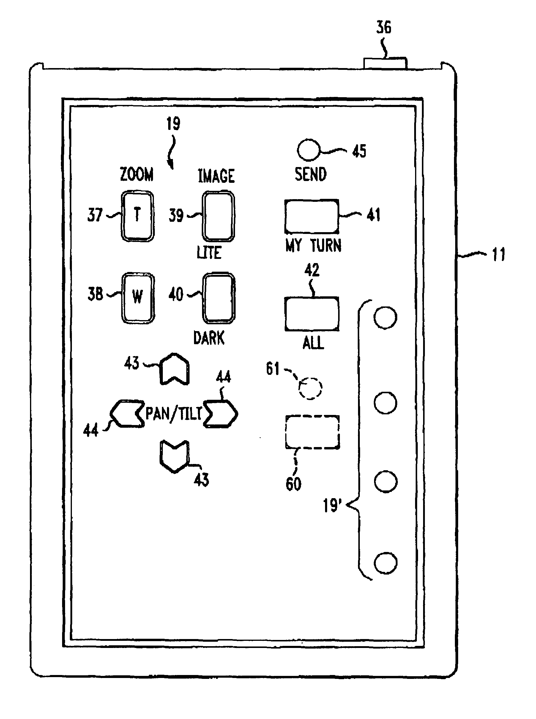
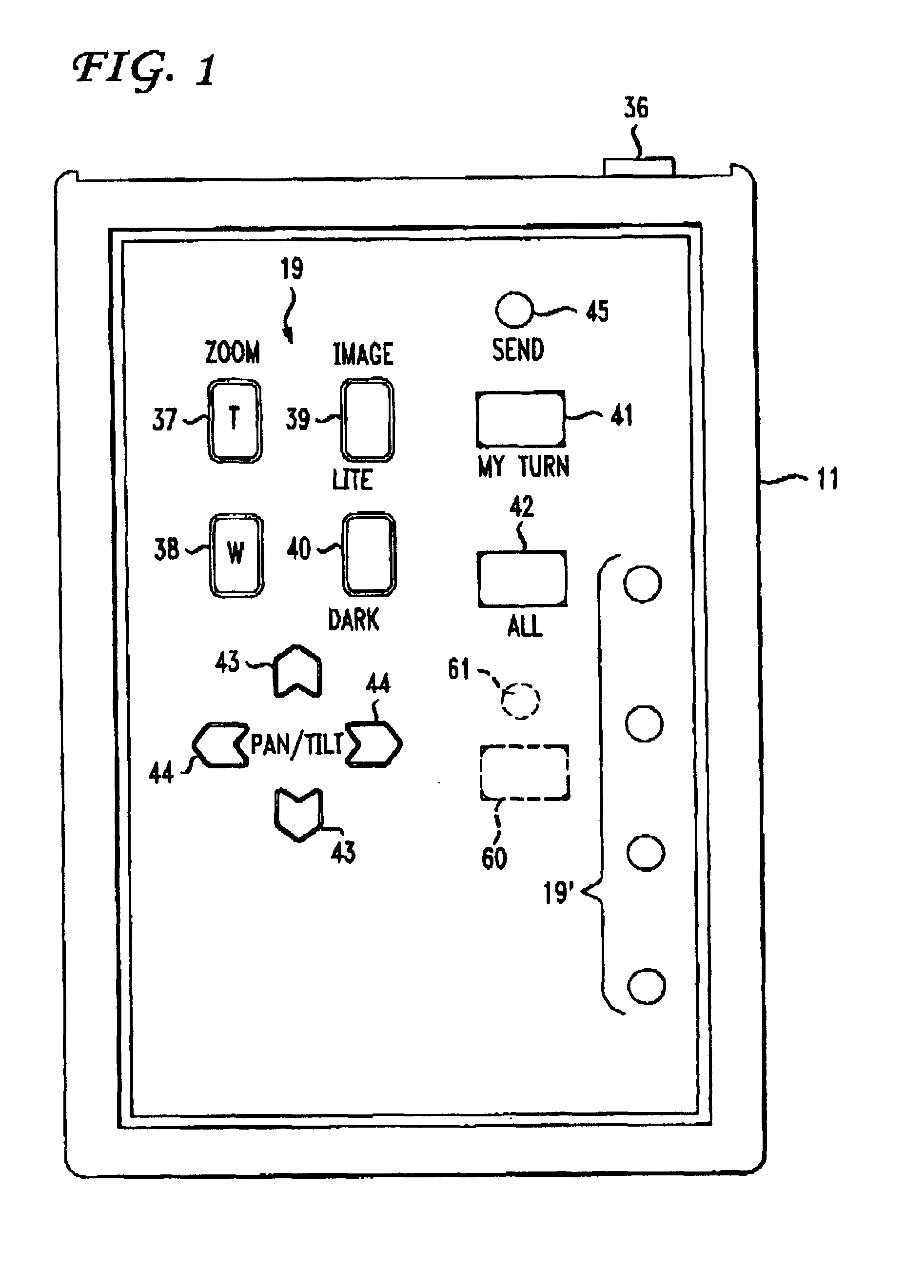
[0008]In one aspect of the present invention there is provided a method of controlling the field of view variables of a camera in a system including a camera, a means for adjusting the field of view variables of the camera and at least two remote control devices capable of sending commands to the means for adjusting the field of view variables of the camera comprising the steps of: remembering at least two specific fields of view of the camera; issuing a field of view command from at least one remote control device; and moving the field of view of the camera to one of the fields of view so remembered. In other aspects of the invention, commands are issued from each of the remote control devices to remember different fields of view of the camera; and remembering the remote control device that issued the respective command. Other steps include moving the field of view of the camera to the field of view remembered associated with the remembered remote control device that issued the respective command; remembering the position of the camera with respect to a known reference; remembering the position in a first plane; and remembering the position of the camera in another plane.
[0009]The present invention also provides the steps of: remembering the zoom perspective of the camera; remembering the focus position of the camera; remembering the iris position of the camera; moving the position of the camera to the remembered position; changing the zoom perspective of the camera to the remembered position; moving the focus position of the camera to the remembered position; and issuing a command by one of the remote control devices to override commands from other remote control devices affecting the field of view of the camera.
[0010]A further aspect of the present invention provides a method of controlling the field of view controls of each camera in a system including at least two cameras, a means for controlling the variables that define the field of view of each camera and at least two remote control devices capable of sending commands to each means for controlling the field of view variables of the respective camera comprising the steps of remembering at least one field of view of each camera; issuing a field of view variable command from at least one of the remote control devices to the means of controlling the cameras; and changing the field of view variables of the camera associated with the field of view remembered to provide the field of view remembered. Other steps include issuing commands from each of the remote control devices to remember a different field of view of the camera; remembering the remote control device that issued the respective command; changing the field of view of the respective camera to the field of view remembered associated with remembered remote control device that issued the respective command; remembering the position of each camera with respect to a known reference; remembering the position of each camera in two planes; remembering the zoom perspective of

Problems solved by technology

The primary drawback of this alternative approach is that no one can be seen clearly in such a wide field of view.

Method used


Image

  • Multi-user camera control system and method
  • Multi-user camera control system and method
  • Multi-user camera control system and method

Examples


Embodiment Construction

General Capability

[0024]The present invention employs a remote tracking system as an option for applications which require remote control of the field of view of a moving picture camera, such as video cameras. A brief review of the design and operation of the prior patent and applications, U.S. Pat. No. 5,268,734, and Ser. Nos. 07 / 736,729; 07 / 875,078; and 08 / 078,434, will be helpful in understanding the technology described herein.

[0025]The base unit of the tracking system transmits an infrared signal through a rotating set of lenses or signal shapers designed to structure the IR beam in a predetermined process. The base unit includes a microprocessor, which monitors indicating circuitry to calculate the error from exact alignment between the base unit and the remote unit. The remote unit transmits a signal to the base unit containing information regarding the received IR signal,particularly the instantaneous strength of the signal so that exact alignment may be achieved. The base u...


PUM


Abstract

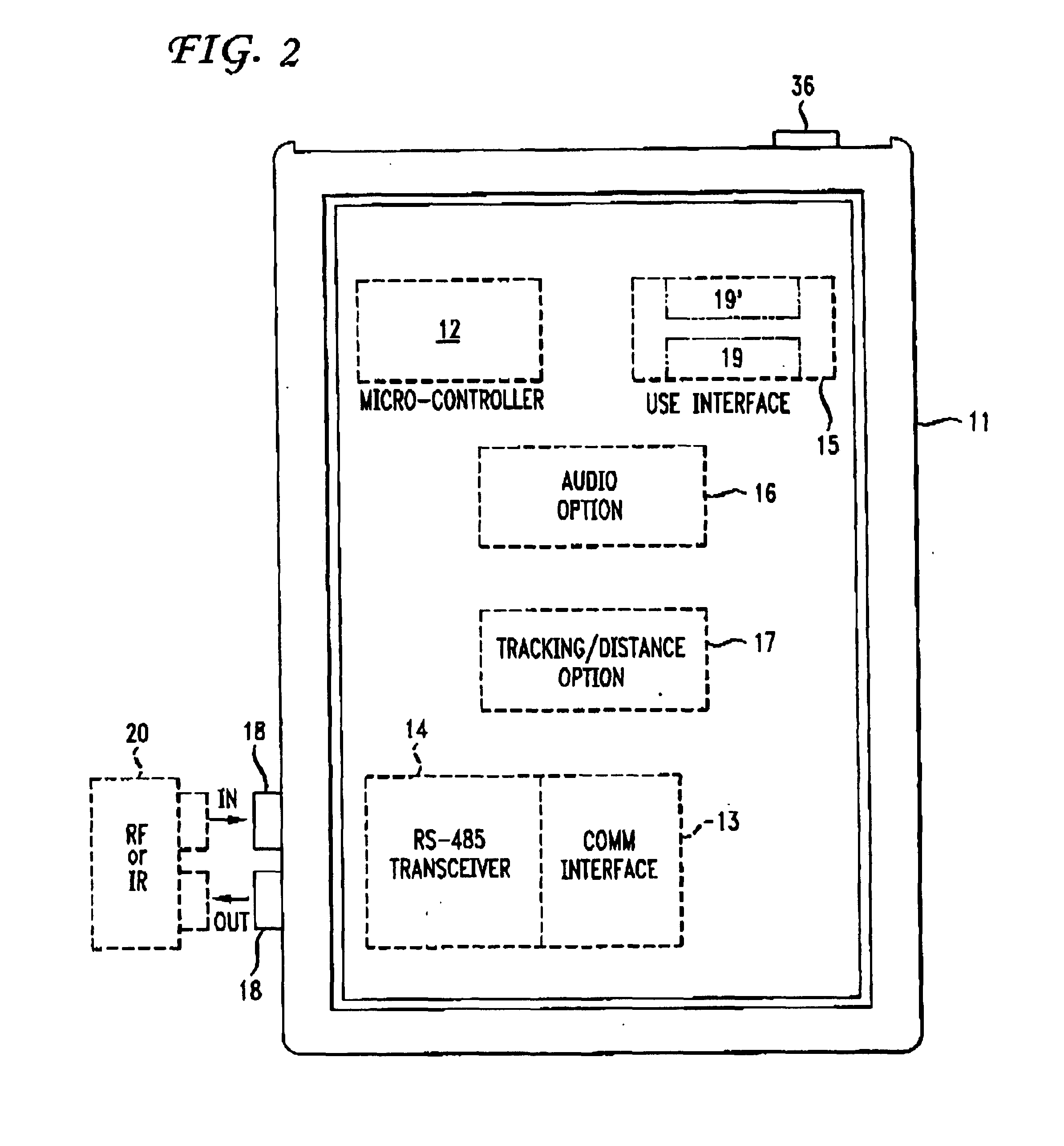
A multi-user camera control system with automatic tracking capability for use in video conferencing and similar applications includes a plurality of personal controllers, one for each person utilizing the system. Each personal controller includes a micro-computer controlled keypad and associated communication circuitry as well as optional audio and tracking capability. The controller is programmed with the capability to send commands to the camera system.The system employs programmed, automatically trackable controllers for issuing commands to control most of the functions of a camera including lens operation. Personal locator devices are electrically connected and can be programmed as a master and as slaves. In addition, a master having override features may be provided, as well as a director's locator device for system wide control.

Description

[0001]This is a division of application Ser. No. 08 / 586,426 filed on Jan. 6, 1996 now U.S. Pat. No. 6,108,035 which is a continuation of application Ser. No. 08 / 255,257 filed on Jun. 7, 1994 now abandoned.BACKGROUND OF THE INVENTION[0002]1. Field of the Invention[0003]The present invention relates to multi-user camera system control particularly for use in video teleconferencing systems, distance learning, audience response, and particularly to user controls for video cameras and associated apparatus in these systems, as well as systems employing automatic tracking capabilities.[0004]2. Prior Art[0005]Current multi-user camera systems in applications such as video conferencing, distance learning, etc. employing cameras have a single point of centralized control with some limited pan, tilt, zoom, and location presents. Having a centralized control generally requires a facilitator to act as a camera operator. This facilitator must decide who or what will be displayed, select a camera,...

Claims


Application Information

Patent Timeline
IPC IPC(8): H04N5/232H04N7/15
CPCH04N7/15
Inventor PARKER, JEFFREY L.SORRELLS, DAVID F.
Owner GVBB HLDG R L
Learn More