Compressible layer for fiber optic cable

a fiber optic cable and compression layer technology, applied in the direction of optical fiber with multi-layer core/cladding, optical waveguide light guide, instruments, etc., can solve the problems of fiber optic cable being susceptible to a unique problem, causing significant pressure on the fiber optic cable within the conduit, signal degradation, etc., to prevent signal degradation, prevent or minimize the movement of the fiber optic core, the effect of preventing signal degradation

Inactive Publication Date: 2006-03-21
AT&T INTPROP I LP
View PDF4 Cites 224 Cited by
  • Summary
  • Abstract
  • Description
  • Claims
  • Application Information

AI Technical Summary

Benefits of technology

[0005]Aspects of the present invention address these problems and others by providing a layered fiber optic cable with at least one compressible layer that can absorb the pressure applied to the cable by ambient water trapped in the conduit as it freezes. Rather than attempt to solve the problem strictly by focusing on preventing water from entering the conduit with the fiber optic cable, the present invention provides a solution that is based on a fiber optic cable that prevents signal degradation when a force is applied to it. By approaching the problem in this manner, even if water enters a conduit and is exposed to freezing conditions, the integrity of the fiber optic cable is maintained. The present invention may even be used in conjunction with the present solutions described above to provide complete confidence in cable reliability during winter months.
[0006]According to one aspect of the present invention, at least one strand of optical fiber forms the axial core of a fiber optic cable. The cable further comprises at least one layer of strengthening material surrounding the core. This material may be aramid yarn to provide tensile strength to the cable. Additionally, the cable has a jacket that encompasses the core and the strengthening layer. The fiber optic cable also has a compressible layer that encompasses the core of the cable. This layer compresses whenever ambient water freezes and applies a force to the cable. By compressing, this layer prevents or minimizes the movement of the fiber optic core of the cable, preventing signal degradation. This compressible layer may be manufactured from elastic materials such as neoprene or closed cell foam. Another aspect of the invention adds a fiber coating layer and a plastic overcoat layer around the cable core.
[0007]According to yet another aspect of the present invention, a method is provided for forming a layered fiber optic cable. The method provides at least one strand of optical fiber for forming the axial core of the cable. At least one layer of strengthening material is provided around the axial core. The strengthening layer is comprised of aramid yarn. A compressible layer is provided around the core to absorb the force applied to the core by the freezing action of ambient water. Neoprene or closed cell foam is used to form the compressible layer. These types of materials additionally provide the interior of the cable with insulation that operates to prevent freezing within the cable. A jacket is provided around the layers of the fiber optic cable.

Problems solved by technology

However, fiber optic cable is susceptible to a unique problem associated with water accumulation around the cable.
However, where the conduit is above the frost line and exposed to freezing temperatures, the water that has accumulated within the conduit freezes, creating significant pressure on the fiber optic cable within the conduit.
This pressure can cause the fiber optic strands within the cable to bend, damaging the fragile glass strands that make up the fiber optic core and leading to signal degradation.
Additionally, the force from the freezing ambient water can cause the glass strands that make up the fiber optic core to break, requiring costly repair.
The problem is amplified when water penetrates the cable itself and freezes or when the glass fibers freeze.
Invariably, due to elevation differences along the length of the conduit, plugged weep holes, or improperly trained personnel, these solutions have met with a limited amount of success.
Additionally, chemical plugs can inhibit access to the cable and make cable removal and repair difficult.
However, this solution is expensive, hard to work with, and not designed for aqueous environments.
However, this solution does not prevent signal degradation due to forces from freezing water surrounding the cable within the protective conduit.

Method used


Image

  • Compressible layer for fiber optic cable
  • Compressible layer for fiber optic cable
  • Compressible layer for fiber optic cable

Examples


Embodiment Construction

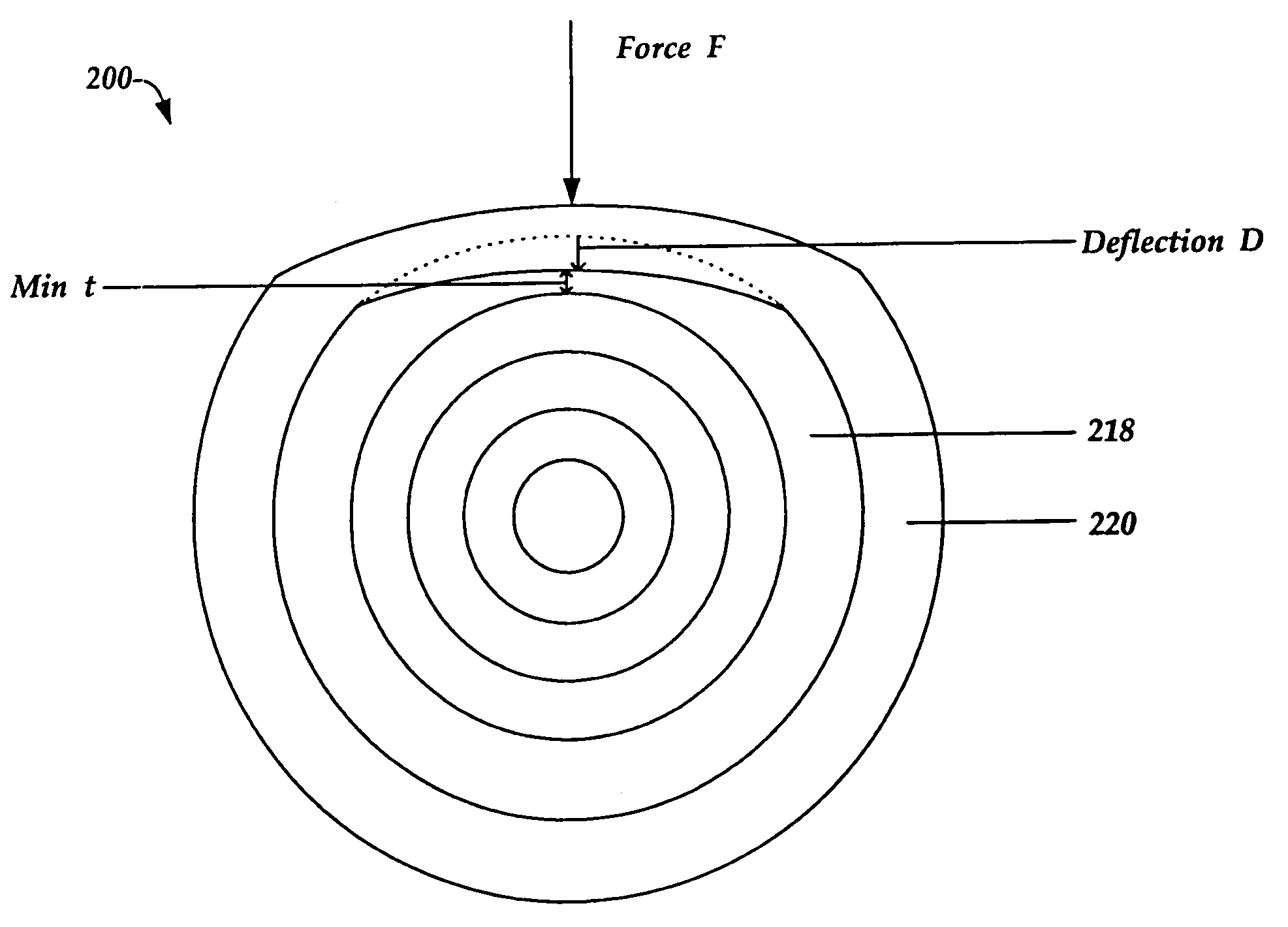
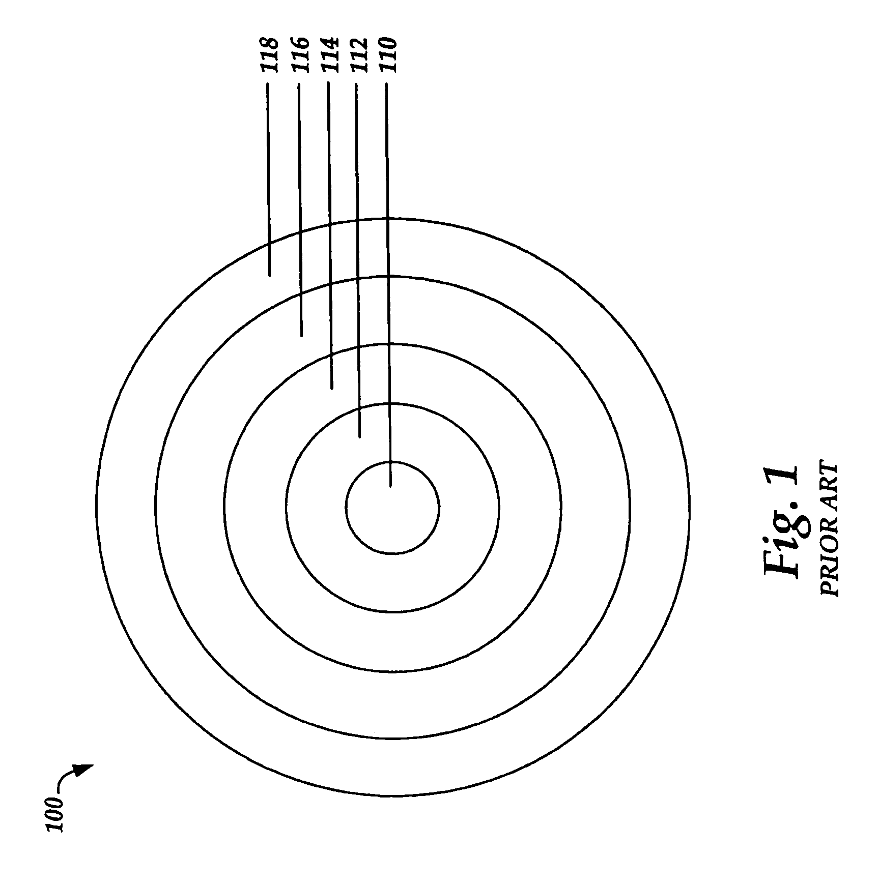
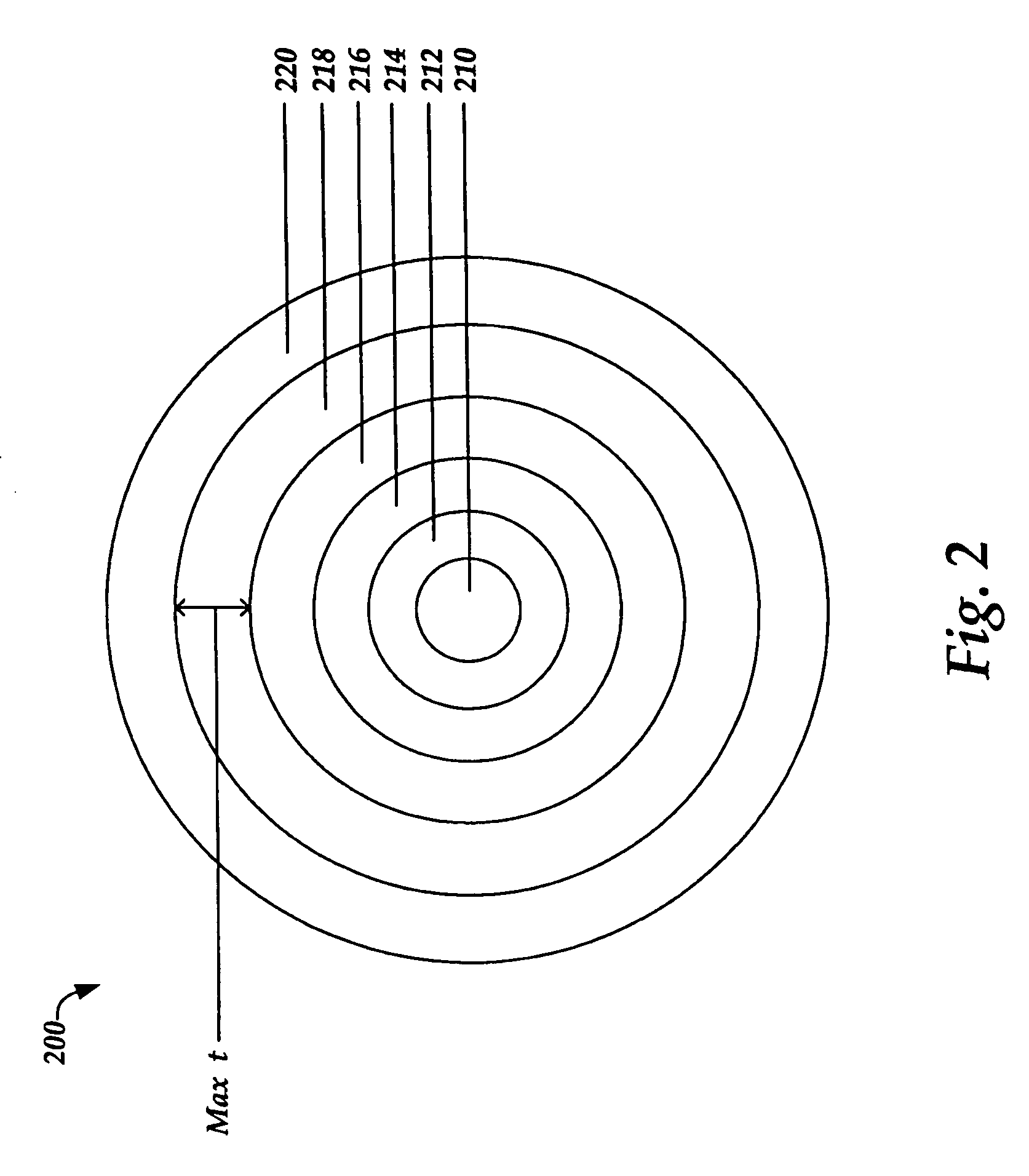
[0012]Signal degradation due to ice-induced bending of the fiber optic strands of a fiber optic cable may be minimized through embodiments of the present invention. FIG. 1 shows the various layers of a typical fiber optic cable 100 as known in the art. The core 110 of the cable is made up of at least one strand of transparent dielectric material, usually glass filament. A layer of fiber coating 112 surrounds the core 110. The fiber coating 112 is made from one or more layers of material of lower refractive index than that of the core. An overcoat 114 surrounds the fiber coating 112. The overcoat 114 is made from plastic or other polymer material. The overcoat 114 may include a high heat resistant thermoplastic resin (not shown). The layer that surrounds the overcoat 114 is the strength member 116. The strength member 116 is a strengthening layer that is included to protect the fiber optic core from excessive tensile and bending stresses. This layer is typically formed from aramid ya...


PUM


Abstract

A layered fiber optic cable having a compressible layer for protecting the fiber optic core from damaging displacement due to force from the freezing of trapped ambient water. As ambient water within a protective conduit freezes, the water expands, applying a force on the fiber optic cable within the conduit. The compressible layer absorbs the expansion of the freezing water by compressing, therefore minimizing displacement of the fiber optic core and resulting signal degradation.

Description

TECHNICAL FIELD[0001]The present invention relates to the protection of fiber optic cable within buried conduit. More particularly, the present invention relates to protecting the fiber-optic core within a fiber optic cable from damage caused by the force placed on the cable from the freezing and consequent expansion of ambient water within the conduit.BACKGROUND OF THE INVENTION[0002]Fiber optic cables provide numerous advantages over traditional communication cables, particularly higher transmission speeds and improved transmission quality. However, fiber optic cable is susceptible to a unique problem associated with water accumulation around the cable. Installation of fiber optic cable typically involves burying conduit between two end locations. The fiber optic cable is then installed within the protective conduit. Water sometimes enters the conduit either through access points in the conduit or through condensation within the conduit. Either way, the water flows downhill and ac...

Claims


Application Information

Patent Timeline
Patent Type & Authority Patents(United States)
IPC IPC(8): G02B6/036G02B6/44
CPCG02B6/4496G02B6/4432G02B6/44386
Inventor DIGGLE, III, FREDERICKRYALS, STEVEN
Owner AT&T INTPROP I LP
Why Eureka
Try Eureka