Method, device and machine for pure bending test optionally alternating

a technology of pure bending and optional alternating, applied in the direction of measuring devices, material strength using repeated/pulsating forces, instruments, etc., can solve the problem of non-negligible amount of error in determining, and achieve the effect of avoiding any risk of inducing parasitic forces

Inactive Publication Date: 2006-03-28
CENT NAT DE LA RECHERCHE SCI
View PDF7 Cites 7 Cited by
  • Summary
  • Abstract
  • Description
  • Claims
  • Application Information

AI Technical Summary

Benefits of technology

[0027]step c) by applying optionally alternating opposing torques in controlled manner about each pivot axis to the respective corresponding grip zones so as to impose optionally alternating opposing bending movements to the bending zones of the two testpieces, while allowing the pivot axes to move freely relative to each other.
[0028]Under such conditions, it is each testpiece which acts via its grip zones interconnected by the bending zone and opposes bending resistance to the bending zone of the other testpiece between its grip zones, without it being necessary to provide any kind of guidance for the grip zones relative to any kind of structure, and consequently avoiding any risk of inducing parasitic forces due to friction into the bending zone of either testpiece. Thus, the measu

Problems solved by technology

This leads to a non-negligible amount of error in determining the changing resistance to bending of the bending zone from a

Method used


Image

  • Method, device and machine for pure bending test optionally alternating
  • Method, device and machine for pure bending test optionally alternating
  • Method, device and machine for pure bending test optionally alternating

Examples


Embodiment Construction

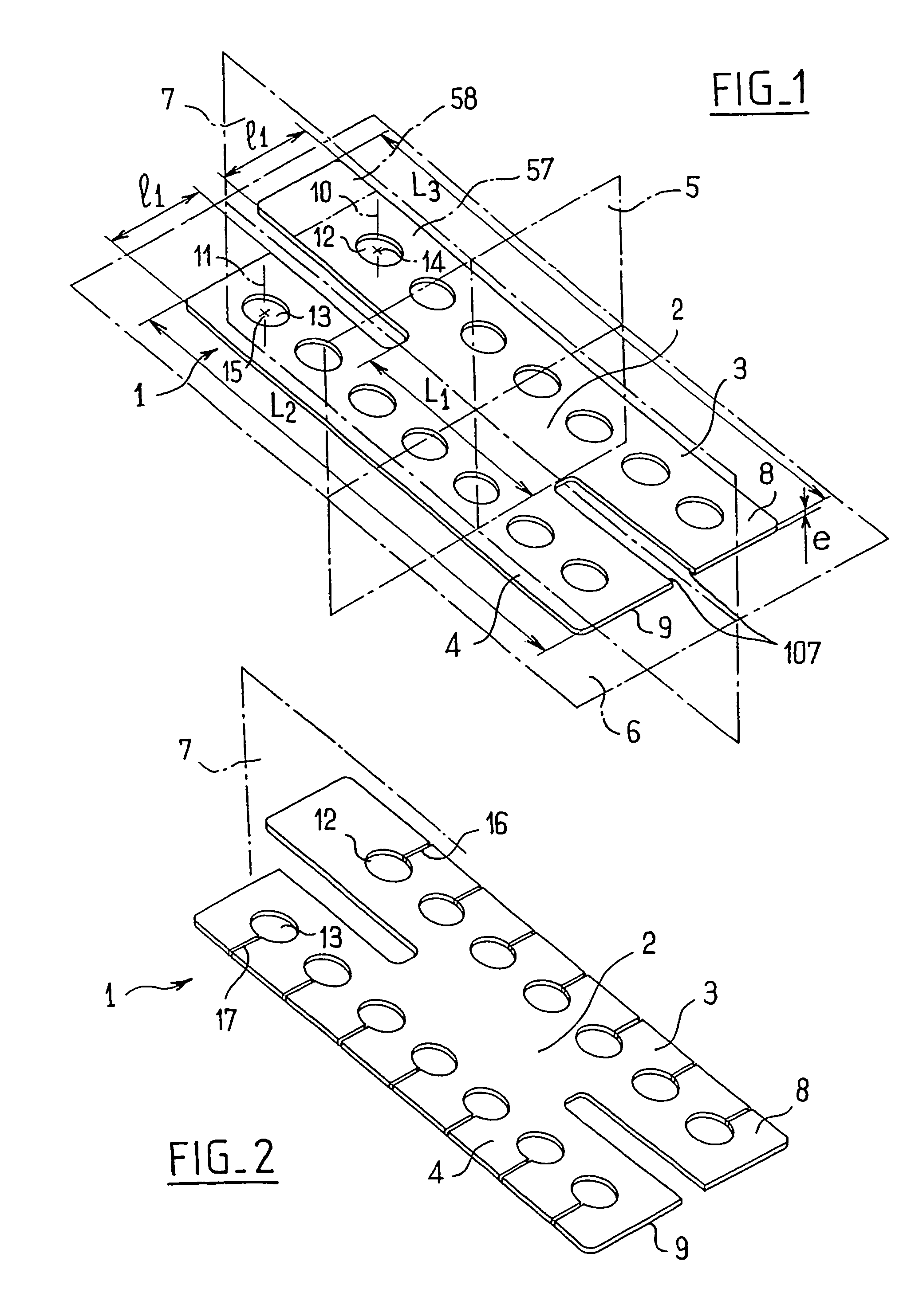
[0108]Reference is made initially to FIG. 1 which shows a testpiece 1 in the rest state, i.e. when subjected to no stress, in particular no bending stress, and comprising a bending zone 2 for being subjected to the alternating bending test, between two end grip zones 3 and 4 which are not themselves subjected to any bending during testing.

[0109]The bending zone 2 presents a first mean plane 5 of symmetry crossing each of the zones 2, 3, and 4 and also constituting a first mean plane of symmetry for the grip zone 4, and a mean surface which is perpendicular to said first mean plane 5 and which, in this example, is plane and constitutes a second mean plane of symmetry 6 for each of the zones 2 and 4, and a mean plane of symmetry for the zone 3. In this example, the bending zone 2 presents a third mean plane of symmetry 7 that it crosses and that intersects the mean planes 5 and 6 at right angles, the grip zones 3 and 4 being disposed respectively on either side of this mean plane 7. I...


PUM


Abstract

The present invention provides a method, apparatus, and a machine for testing in pure bending, optionally in alternating bending. Two mutually identical testpieces are subjected to optionally alternating opposing bending movements while conserving mutual symmetry about a point, under drive from two controlled motor assemblies that are free to move relative to each other. Interfering forces induced in the two testpieces during testing are minimized, and the performance of the testpieces in pure bending can be studied with increased accuracy.

Description

CROSS REFERENCE TO RELATED APPLICATIONS[0001]The present application is a national phase entry under 35 U.S.C. § 371 of International Application No. PCT / FR03 / 02515 filed Aug. 12, 2003, published in France, which claims priority from French Application No. 02 / 10261 filed Aug. 31, 2002, all of which are incorporated herein by reference.[0002]This application is a 371 of PCT / FR03 / 02515.[0003]The present invention relates to a method of testing in pure bending, optionally in alternating bending, the method comprising the following succession of steps:[0004]a) making or selecting a testpiece having two mutually opposite end grip zones and a bending zone interconnecting the two grip zones, said testpiece presenting, in a rest state, a first mean plane crossing the bending zone and each of the grip zones and constituting a first plane of symmetry at least for the bending zone, and a mean surface for the bending zone and each of the grip zones, which mean surface is perpendicular to the fi...

Claims


Application Information

Patent Timeline
IPC IPC(8): G01N3/20G01N3/00G01N3/04G01N3/32
CPCG01N3/20G01N3/32G01N2203/0007G01N2203/0476G01N2203/0075G01N2203/0405G01N2203/0023
Inventor CALLOCH, SYLVAINDUREISSEIX, DAVIDARNOLD, GILLESZUDAIRE ROVIRA, INAKI
Owner CENT NAT DE LA RECHERCHE SCI
Why Eureka
Try Eureka