
Method for detecting a rollover situation

a rollover situation and situation detection technology, applied in the field of rollover situation detection, can solve the problems of high response sensitivity, spurious triggering, and failure to trigger the decision

Inactive Publication Date: 2006-03-28
CONTINENTAL AUTOMOTIVE GMBH
View PDF12 Cites 12 Cited by
  • Summary
  • Abstract
  • Description
  • Claims
  • Application Information

AI Technical Summary

Benefits of technology

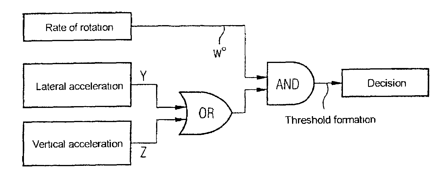
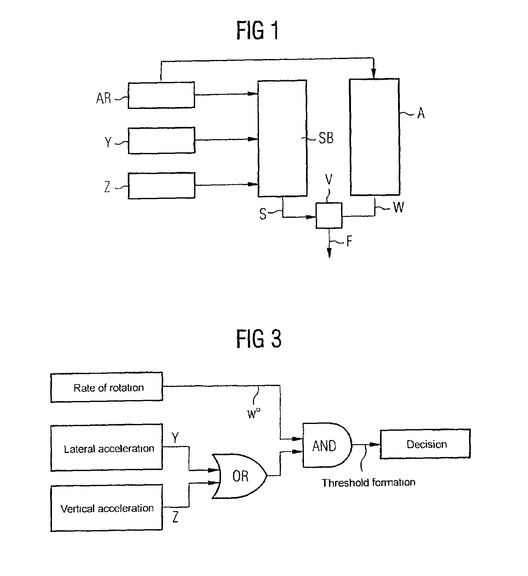
[0022]Two sensor signals are used to make the triggering decision. The, at least two sensor signals are also used to provide a safing function at the same time. Safing means that a spurious triggering as a result of faulty components, e.g. of a sensor, is prevented. A triggering with only one sensor signal is not possible, which prevents undesired triggering from occurring in the event of a single fault with one sensor.

Problems solved by technology

A combination of these sensor signals and a comparison with a threshold value is used to decide upon a triggering of the restraint means, which either leads to a high sensitivity of response and corresponding spurious triggerings (misuse) or leads to the triggering decision not being made at the right time.

Method used


Image

  • Method for detecting a rollover situation
  • Method for detecting a rollover situation
  • Method for detecting a rollover situation

Examples


Embodiment Construction

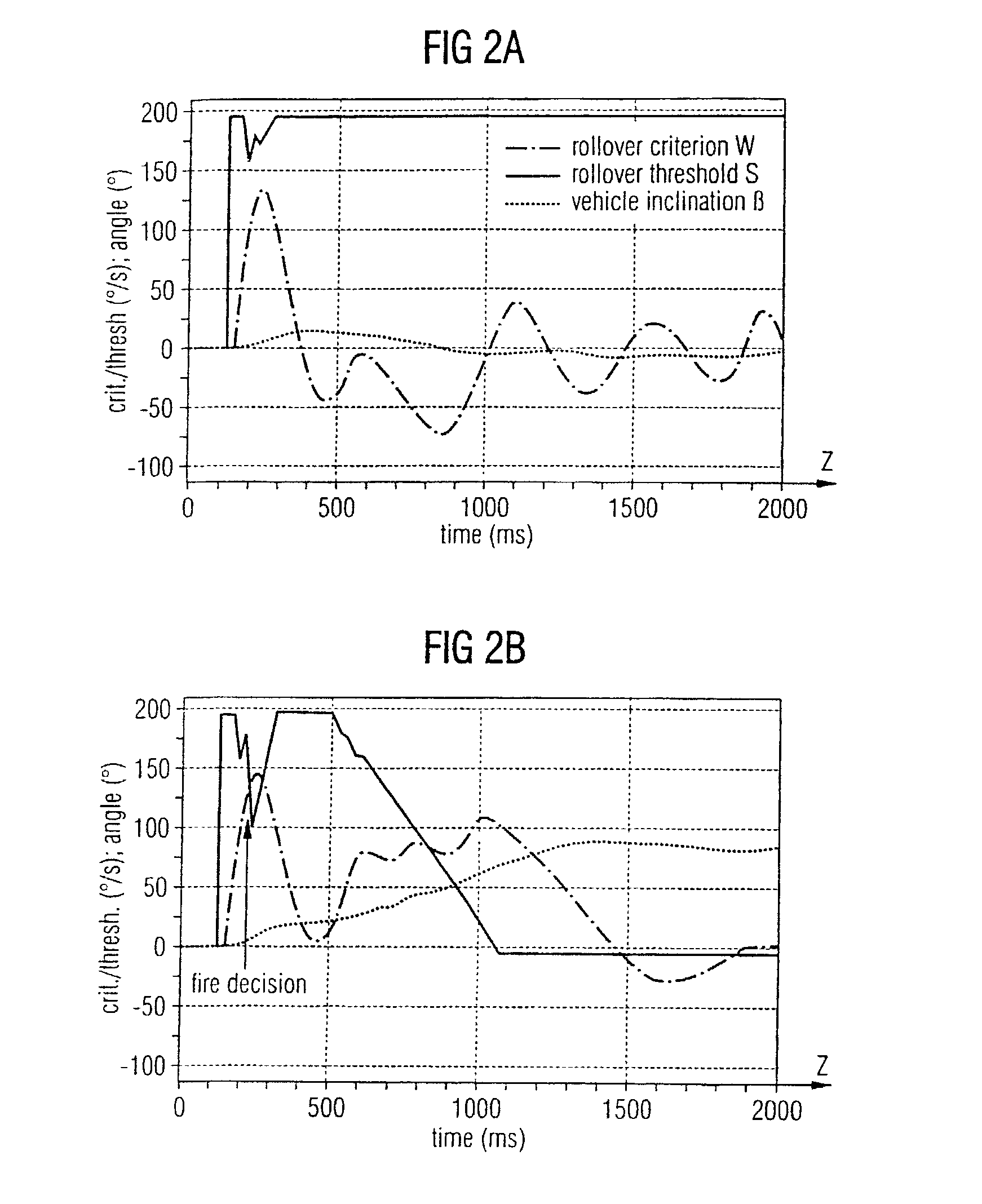
[0029]In FIG. 1, sensors Y, Z for the detection of vehicle accelerations in the vehicle transverse axis (Y-direction) and the vertical vehicle axis (Z-direction) and a rate of rotation sensor AR for detecting the speed of rotation of the vehicle about the vehicle longitudinal axis (X-axis) are shown. The signals from the sensors Y, Z, AR are evaluated by a threshold value generator SB, which forms a dynamic rollover threshold S in accordance with a predefined algorithm. A matching element A determines the angular speed W about the vehicle longitudinal axis from the signal of the rate of rotation sensor AR. A comparator V, which can be arranged in an airbag control unit ECU, for example, sends a firing command F to a downstream restraint means when the angular speed W exceeds the rollover threshold S.

[0030]The device shown in FIG. 1 is part of an occupant restraint system of a vehicle, for example.

[0031]Different vehicle situations are shown in FIGS. 2A and 2B:

[0032]The vehicle incli...


PUM


Abstract

The invention relates to a method for detecting a rollover situation in such a way that a restraint, such as belt tighteners or head airbags, can be released at the right time during rollover. The signals that pertain to several sensors and detect transitional and rotational movements are detected, connected to one another and evaluated.

Description

CLAIM FOR PRIORITY[0001]This application claims priority to International application No. PCT / DE01 / 00293 which was published in the German language on Sep. 7, 2001.TECHNICAL FIELD OF THE INVENTION[0002]The invention relates to a method for detecting a rollover situation.BACKGROUND OF THE INVENTION[0003]Previous systems only compare the sensor signals provided by the sensors for detecting a rollover situation with a fixed threshold or only set sensor signals from sensors of the same type against one another. A combination of these sensor signals and a comparison with a threshold value is used to decide upon a triggering of the restraint means, which either leads to a high sensitivity of response and corresponding spurious triggerings (misuse) or leads to the triggering decision not being made at the right time.SUMMARY OF THE INVENTION[0004]In one embodiment of the invention, sensor signals are linked with a threshold value and one another to perform a triggering decision if a sensor ...

Claims


Application Information

Patent Timeline
Patent Type & Authority Patents(United States)
IPC IPC(8): B62D49/08B60R22/46B60R21/00B60R21/01B60R21/0132B60R21/16B60R21/20B60R21/213B60R21/214
CPCB60R21/013B60R21/0132B60R2021/01327B60R2021/01027B60R2021/01325B60R2021/0018B60R21/01
Inventor FRIMBERGER, MANFREDWOLF, FLORIAN
Owner CONTINENTAL AUTOMOTIVE GMBH
Learn More