
Recreational vehicle locking differential

Inactive Publication Date: 2006-03-28
ARCTIC CAT
View PDF16 Cites 16 Cited by
  • Summary
  • Abstract
  • Description
  • Claims
  • Application Information

AI Technical Summary

Benefits of technology

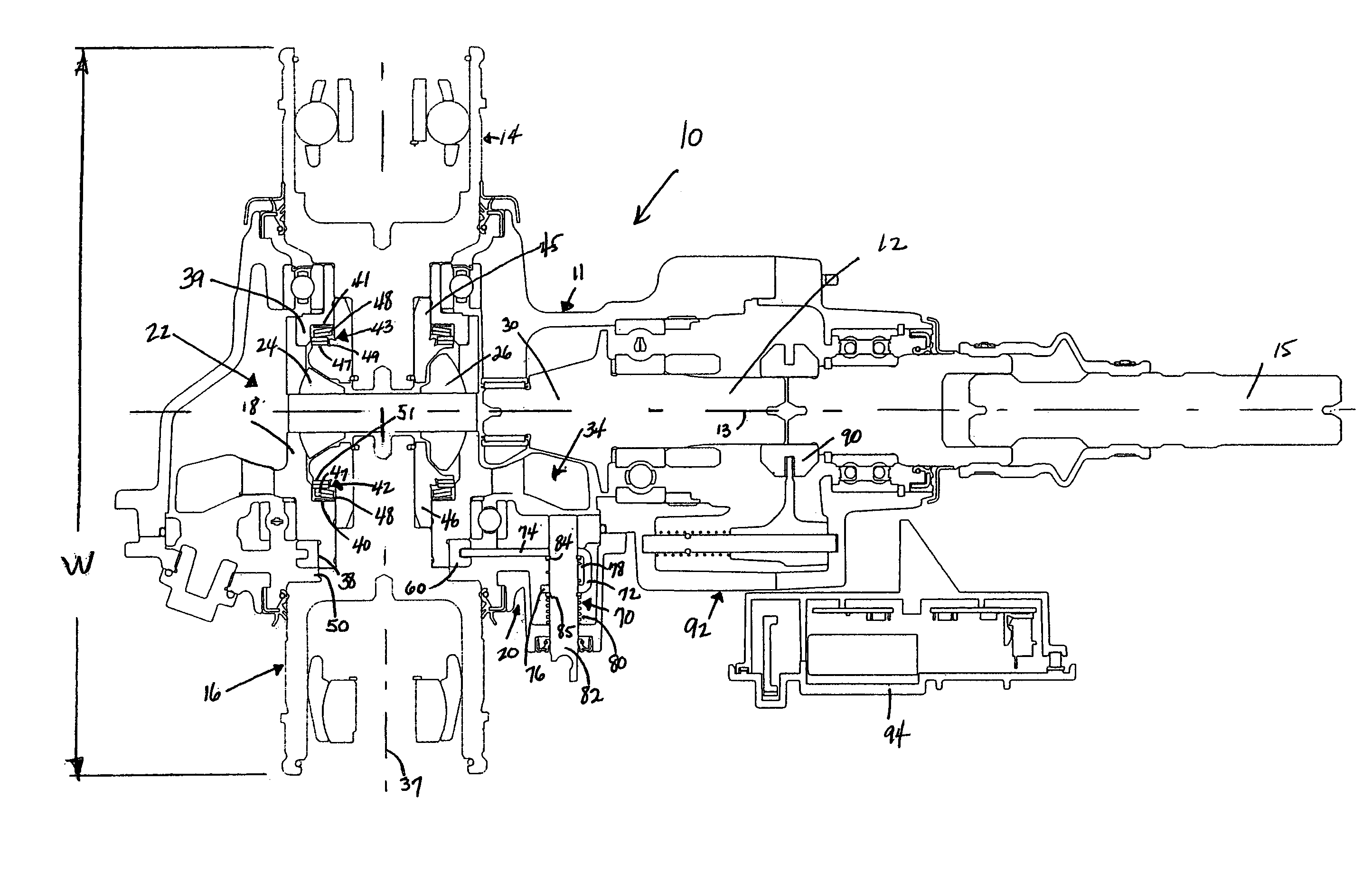
[0009]Another aspect of the invention relates a method of controlling allocation of power in an ATV. The ATV includes a transmission assembly having a rear transmission portion and a rear set of wheels driven by the rear transmission portion. The rear transmission portion includes a rear differential and a rear locking coupler configured to lock the rear differential. The method includes adjusting the rear locking coupler between a locked and an unlock position to control allocation of power from an engine of the ATV to the rear wheels. Locking the rear differential assembly with the rear locking coupler provides equal allocation of power from the engine to the rear wheels, and unlocking the rear differential assembly with the rear locking coupler facilitates variable allocation of power from the engine to each of the rear wheels.

Problems solved by technology

One disadvantage of differential joints is that they typically add additional width to the vehicle transmission and / or track.
For this and other reasons, there has not been an effective differential joint put into practice for an ATV rear-end transmission portion.
One disadvantage of most locking mechanisms is that they tend to widen the vehicle transmission and / or track width.
As discussed above, a wider transmission and / or track may have undesirable limitations in some applications.
Another disadvantage of some locking mechanisms is their complexity in design and the inherent reworking of the transmission that is required to implement the locking mechanism into the transmission.

Method used


Image

  • Recreational vehicle locking differential
  • Recreational vehicle locking differential
  • Recreational vehicle locking differential

Examples


Embodiment Construction

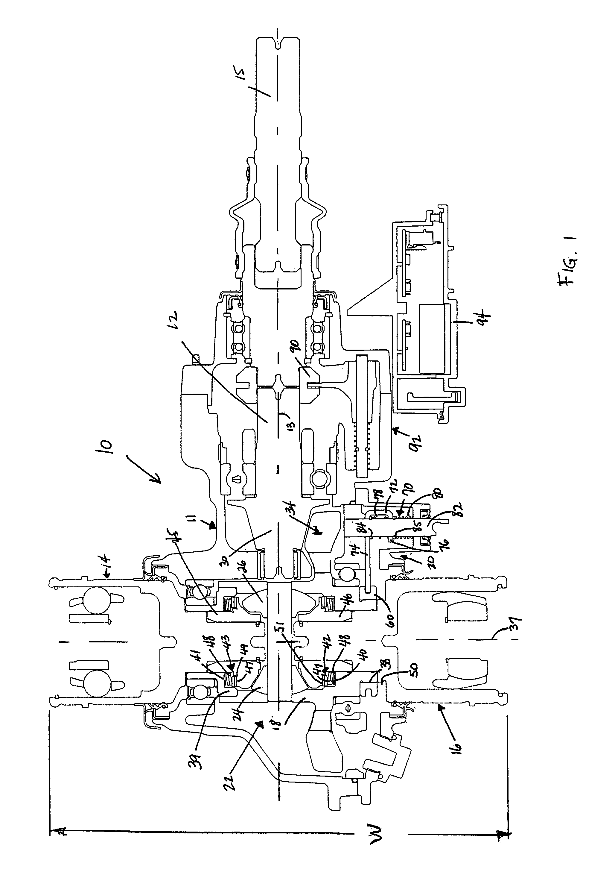
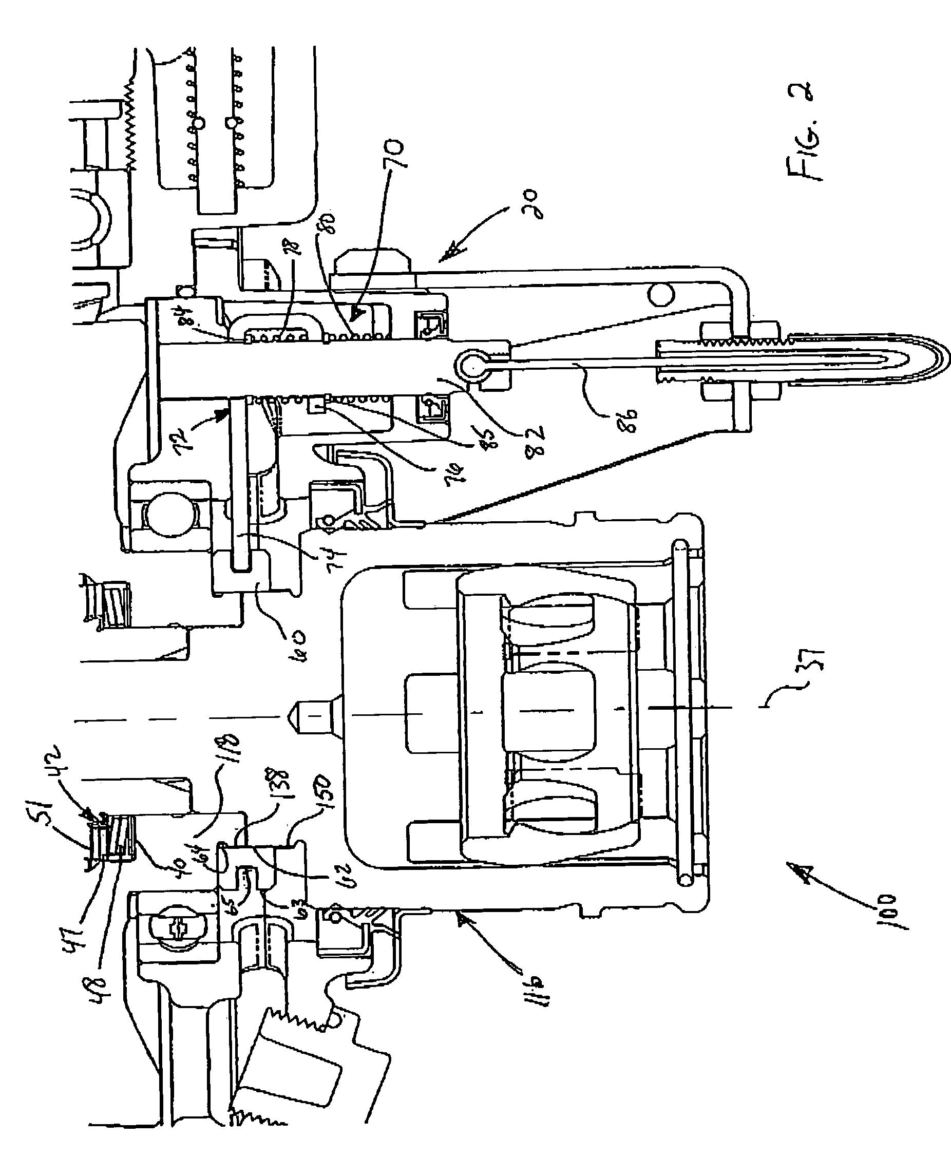
[0017]The present invention relates to a rear transmission having differential capabilities, and locking mechanisms for locking differential joints of a vehicle transmission. Differential joints are typically associated with front-end portions of an all-terrain vehicle (ATV) vehicle transmission to improve the turning radius and ease in turning the vehicle. One aspect of the invention relates to an ATV transmission that includes a rear transmission assembly that includes a rear differential joint coupled to rear wheels of the ATV. A rear differential may also improve the turning radius and ease in turning the vehicle either in combination with a front differential or when used alone. Another aspect of the invention relates to a rear locking coupler that is configured to lock the rear differential to fix rotation of the rear wheels together for improved power distribution to the rear wheels.

[0018]The locking coupler of the present invention may include an inner surface configured to ...


PUM


Abstract

The present invention relates to a transmission for a recreation vehicle, such as an all-terrain vehicle that includes a locking assembly for locking a differential joint in the front- or rear-end portion of the transmission. A vehicle having both front and rear differentials may include separate locking assemblies for each differential to lock and unlock the differentials for various combinations of power allocation to wheels of the vehicle. A differential joint according to the invention may include a ring gear and spider gears that drive a universal joint coupled to wheels of the vehicle. A coupler of the locking assembly includes an inner surface configured to engage outer surfaces of the ring gear and the universal joint, and an outer surface configured to be engaged by an actuator. The actuator adjusts the coupler between a locked position wherein the ring gear and the universal joint are locked together, and an unlocked position wherein the universal joint is free to rotate relative to each other. The coupler preferably has a relatively thin width so as to minimize a track width of the vehicle.

Description

BACKGROUND OF THE INVENTION[0001]1. Field of the Invention[0002]The present invention relates to all-terrain vehicle (ATV) drive systems, and more specifically relates to differential joints for a rear transmission and to locking mechanisms for locking differential joints to universal joints of a vehicle transmission.[0003]2. Related Art[0004]Most powered vehicles with front end steering capabilities include some type of differential joint and an associated pair of universal joints, such as a constant velocity (CV) joints, positioned on opposing sides of the differential joint in a front end portion of the transmission assembly. A differential joint facilitates rotation of the opposing universal joints at different speeds. This feature is particularly useful when turning a vehicle because it facilitates a smaller turning radius with less friction resistance between the wheels and a surface over which the vehicle moves.[0005]One disadvantage of differential joints is that they typica...

Claims


Application Information

Patent Timeline
IPC IPC(8): F16H48/24B60K17/16B60K17/346F16H48/08F16H48/30
CPCB60K17/16B60K17/346F16H48/30F16H48/24F16H48/08
Inventor TWEET, OLESTENVIK, OWEN
Owner ARCTIC CAT
Learn More