Process and device for the aligning of workpiece with pre-cut teeth on gear finishing machines

a technology for gear finishing machines and workpieces, which is applied in the direction of gear teeth, electrical/magnetic measuring arrangements, using electrical/magnetic means, etc., can solve the problems of machining operations that fail to embrace the entire flank surface, aligning errors, and complicated fine machining of the tooth flanks in particular, so as to achieve the effect of reducing effort and expenditur

Inactive Publication Date: 2006-04-04
REISHAUER
View PDF16 Cites 19 Cited by
  • Summary
  • Abstract
  • Description
  • Claims
  • Application Information

AI Technical Summary

Benefits of technology

[0007]The object of the present invention is to provide a process and a device by which, for the aligning of the teeth of a precut gear on a gear finishing machine, the aligning accuracy can be kept within close tolerance limits during the series production of a workpiece with little effort and expenditure.

Problems solved by technology

In this process the fine machining of the tooth flanks in particular is a complicated, resource consuming, and hence expensive operation.
Practical experience shows, however, that in the course of series production aligning errors occur according to a time trend due to thermal or other physical influence.
The result is differing material removal on the left and right flanks, or scrap as soon as due to the scant machining allowance the finish machining operation fails to embrace the entire flank surface on some flanks.
On account of the complex machine construction and processing sequence, and of the numerous physical factors of influence intrinsic to the process, the causes of such alignment errors varying to a trend pattern during series production can mostly only be determined and brought under control at great expense.
In some cases the only method is the interruption of the production process and the repetition of the teach-in operation by the setter or the operator, by which production is considerably impaired and made more expensive.
The necessity for this is often not realized until a substantial amount of scrap has already been produced.

Method used


Image

  • Process and device for the aligning of workpiece with pre-cut teeth on gear finishing machines
  • Process and device for the aligning of workpiece with pre-cut teeth on gear finishing machines

Examples


Embodiment Construction

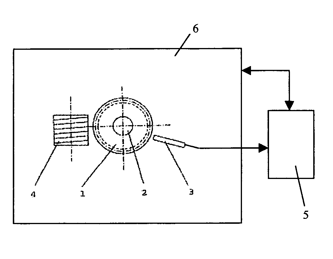
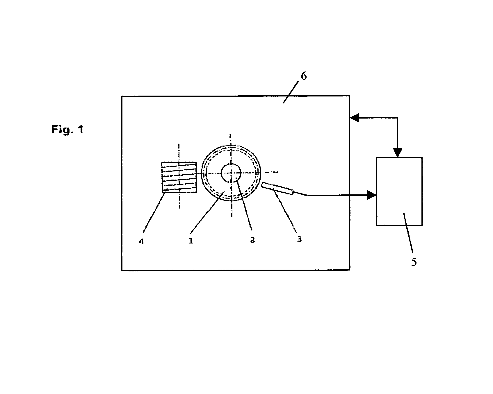
[0019]FIG. 1 depicts the diagrammatic plan view arrangement of workpiece 1, aligning probe 3 and machining tool 4 on a gear manufacturing machine 6 for the finish machining machine or workpieces with precut teeth. Typical machining tools are for example grinding worms, grinding wheels, milling cutters, honing tools and the like.

[0020]The beginning of an automatic machining cycle corresponds with the procedure in accordance with the background of the invention described at the outset. Firstly, by means of a loading device not shown, a workpiece blank 1 is fitted and clamped in known manner on the spindle 2. After clamping, the spindle 2 is put into rotation, and in known manner by means of an aligning probe 3 the angular positions of the workpiece tooth flanks relative to the stationary aligning probe 3 are measured. From the measured data the machine control system calculates a mean value for the angular positions of all the tooth spaces. Then the workpiece 1 is rotated through the ...


PUM

PropertyMeasurementUnit
temperatureaaaaaaaaaa
depthaaaaaaaaaa
outer diameteraaaaaaaaaa

Abstract

The invention concerns a process for the aligning of the tooth spaces of workpieces (1) with precut teeth, which are set up for fine machining on the work spindle (2) of a gear finishing machine. In order to avoid the trend related occurrence of out-of-tolerance aligning errors as series production progresses, teach-in cycles are performed on the workpiece machined in the immediately preceding machining cycle, called for automatically after time intervals or machining cycle intervals which are either pre-defined or calculated by the machine control system. By this means any prevailing trend errors are restored to zero.

Description

FIELD OF THE INVENTION[0001]The present invention concerns a process and a device for the alignment of the tooth spaces of pre-machined workpieces, which are set up for fine machining on the work spindle of a gear finishing machine.BACKGROUND OF THE INVENTION[0002]Increased demands on the running qualities of gears in gear drives require more and more the precision finish machining of the gear teeth. In most cases the pre-machined workpieces are case-hardened, and then fine machined to the finished dimensions on all their functional surfaces. In this process the fine machining of the tooth flanks in particular is a complicated, resource consuming, and hence expensive operation. In the interests of economic manufacture, but also in order to avoid having to provide for unnecessarily large hardening depths and to balance and minimize the wear on the left and right flanks of the fine machining tool, it is therefore attempted to keep the material allowance for the fine machining as small...

Claims


Application Information

Patent Timeline
Patent Type & Authority Patents(United States)
IPC IPC(8): G01B5/16B23F19/00B23F23/12B23F23/00
CPCB23F23/006B23F19/00
Inventor GRAF, JURGOHM, RENE
Owner REISHAUER
Why Eureka
Try Eureka