
Shipping and display carton

Inactive Publication Date: 2006-04-04
MEADWESTVACO PACKAGING SYST LLC
View PDF21 Cites 75 Cited by
  • Summary
  • Abstract
  • Description
  • Claims
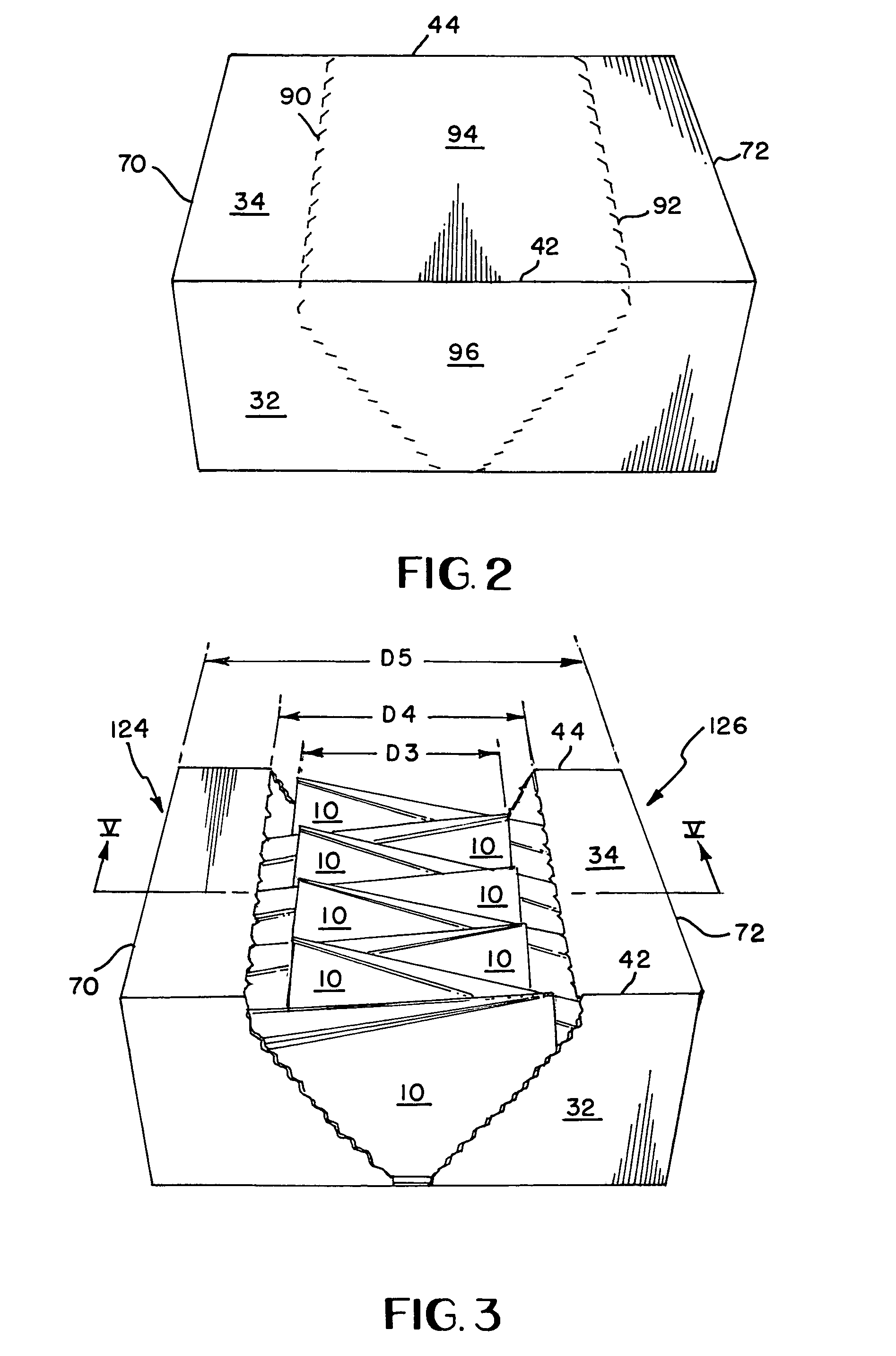
  • Application Information

AI Technical Summary

Benefits of technology

[0007]The invention also contemplates separating the carton or package along lines of weakening to convert the carton into two display trays with the opposed side walls of the original carton forming the respective bottoms of the trays. This arrangement makes it possible to utilize the carton as a display device for the articles at the retail sales outlet.
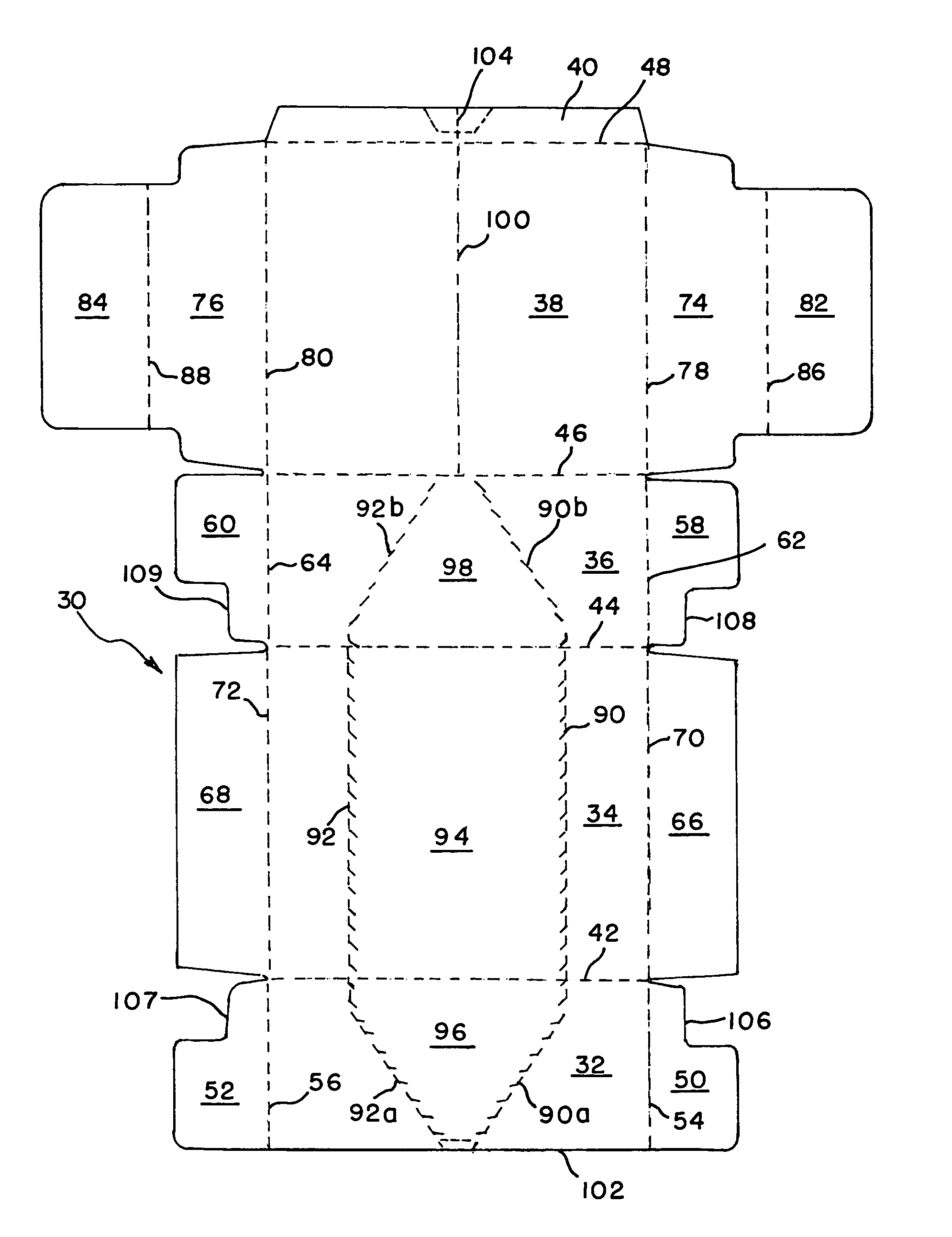
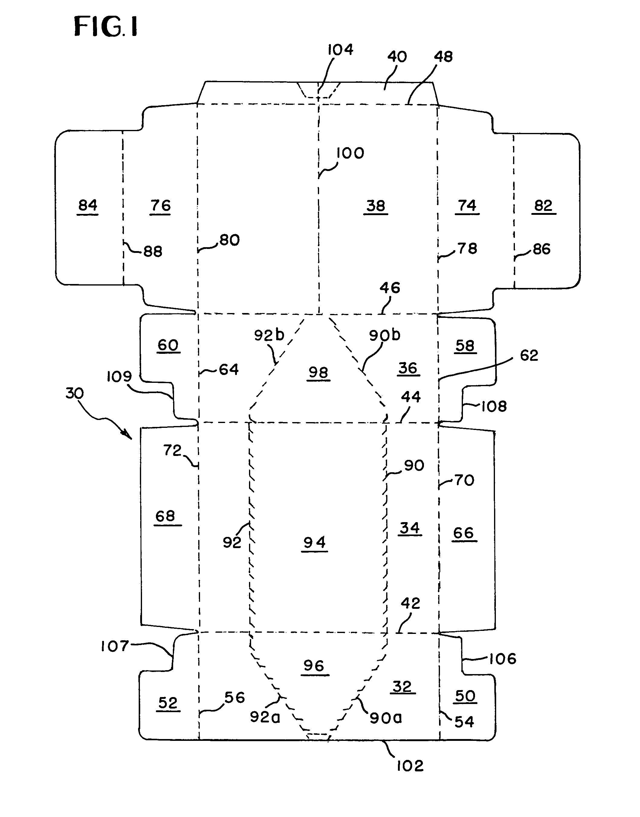
[0008]The present invention further contemplates pivoting the two divided sections of the carton about a fold line without disturbing each row of the packaged articles. The fold line is formed in the base of the carton whereas lines of weakening are formed in the top, front and rear of the carton. The top of the carton is provided with a pair of juxtaposed weakened lines or tear lines that are located generally at an equal distance from the fold line in the base. The tear lines in the top extend all the way across the top to define between themselves a removable portion. The distance between the fold line and either tear line of the top is dimensioned such that the two rows of articles may be efficiently separated or uninterleaved from each other while held in the respective sections of the carton when the two sections are pivoted about the fold line.
[0009]Accordingly, the present invention in one aspect provides a package including a carton and a group of tapered articles accommodated in the carton. The carton includes a top wall, front and rear walls extending downwardly from the front and rear edges of the top wall respectively, a base wall extending between the respective lower edges of the front and rear walls, and a pair of opposed side walls extending downwardly from the side edges of the top wall to said base wall. Each article in the group has a top that is less in thickness than its bottom. In the carton, the articles are arranged in two rows that are disposed along the side edges of the top wall respectively. The bottoms of the articles in one row face one of the side walls of the carton whereas the bottoms of the articles in the other row face the other side wall of the carton. The tops of the articles in the one row are disposed in an overlapping nested relationship with the tops of the articles in the other row. The top wall of the carton is formed with a pair of juxtaposed tear lines extending between the front and rear edges of the top wall to define therebetween a first removable portion. The base wall of the carton is formed with a fold line disposed substantially parallel to the tear lines of the top wall. The fold line of the base wall extends between the lower edges of the front and rear walls. Each of the front and rear walls is formed with at least one tear line so that the carton is separable into two display trays with the side walls forming bottoms of said display tray when the removable portion is removed and the base wall is folded double along its fold line. The distance between the fold line of the base wall and either one of the tear lines of the top wall is greater than a maximum distance between the fold line of the base wall and the tops of the articles in either row so that the base wall may be folded about the fold line without causing interference between either one of the display trays and the articles in the other tray.

Problems solved by technology

Because of the irregular configuration of a pouch discussed above, packaging a quantity of pouches for shipment or the display of multiple pouches has always been a problem.
This arrangement, due to the irregular shape of the pouches, resulted in larger shipping cartons which increased the cost for manufacturing since more material was required.
This way of separation, however, would result in two discrete trays that are subject to mutual displacement, which does not always agree with the tidy appearance required of a display device at retail stores.
During the pivotal movement, either section of the carton would interfere at its top with the pouches on the other section such that efficient separation of the two rows is hindered.
This would result in dislodging of some of the pouches from the display trays during the conversion of the carton into the trays.

Method used


Image

  • Shipping and display carton
  • Shipping and display carton
  • Shipping and display carton

Examples


second embodiment

[0042]FIG. 11 illustrates a blank for forming a carton of the second embodiment according to the present invention while FIG. 12 illustrates a package formed from the blank of FIG. 11 and the aforementioned two-row group of pouches. In these drawings, like parts have been designated by the same reference numeral with the prefix “2” and only the differences are discussed in any greater detail in the following description.

[0043]Referring to FIG. 11, the blank 230 as a whole is generally rectangular in shape. A rectangular front wall panel 234 is centrally located in the blank 230 and flanked by a pair of opposed side wall panels 210 and 212 along fold lines 270 and 272. Base wall panel portions 238a, 238b, 238c and 238d are hingedly connected to the front, rear and side wall panels 232, 236, 210 and 212 along fold lines 310, 246, 312 and 314 respectively. These panel portions 238a, 238b, 238c and 238d cooperate together to form a base wall when the blank 230 is erected into a carton a...

first embodiment

[0045]The way the package of FIG. 12 is formed is substantially different from the way in which the package of the first embodiment is formed particularly in that the blank 230 is designed to be delivered to a packager (e.g., a bottler) in its intact blank form so that the entire package-forming process is carried out by the packager.

[0046]To form the package of FIG. 12, the two-row group of pouches is placed on the top wall panel 234 with the pouches' side panels facing down and the two rows of pouches being disposed along the fold lines 270 and 272 respectively. Then, the front wall panel 232, the base wall panel portion 238a and the web structures 316 and 318 are folded about the fold line 242 to take an upright position alongside the endmost pouches in the first and second rows. Simultaneously, the rear wall panel 236, the base wall panel portion 238b and the web structures 320 and 322 are folded about the fold line 244 to take an upright position alongside the other endmost pou...


PUM


Abstract

The carton is convertible into two display trays on which tapered articles may be displayed. The trays can be pivoted about a fold line without disturbing each row of articles in the carton. The fold line is formed in the base of the carton whereas lines of weakening are formed in the top, front and rear. The top of the carton is provided with a pair of parallel weakened or tear lines that are parallel to the fold line in the base. The tear lines in the top extend all the way across the top to define between themselves a removable portion. The distance between the fold line and either tear line of the top is dimensioned such that the two rows of articles may be efficiently separated or uninterleaved from each other while held respectively in the two trays when the two trays are pivoted about the fold line.

Description

[0001]This application claims the benefit of Provisional Application No. 60 / 366,856 filed Mar. 22, 2002.BACKGROUND OF THE INVENTION[0002]The present invention relates generally to a carton for the storage, shipping and display of articles, and more particularly, to a carton which is convertible from a substantially closed form to an opened form for displaying articles, especially articles in the form of tapered primary containers, such as stand-up pouches. The carton of this invention is formed with weakened lines or tear lines for facilitating the carton being opened and divided into two sections connected along a fold line. The two sections of the carton are then pivoted to a position alongside of each other to expose the articles in a manner to effectively display the articles.[0003]Pouches are used for packaging a variety of products in liquid or in dry form. A typical stand-up pouch has a generally flat bottom to support the pouch in its stand-up position and is tapered to the ...

Claims


Application Information

Patent Timeline
IPC IPC(8): B65D1/22B65B5/06B65B5/08B65B5/10B65D5/20B65D5/50B65D5/52B65D5/54
CPCB65B5/061B65B5/08B65B5/10B65B5/106B65D5/545B65D5/5004B65D5/5253B65D5/542B65D5/208
Inventor CARGILE, JR., JOHN W.
Owner MEADWESTVACO PACKAGING SYST LLC
Learn More