Cryoplasty device and method

a technology of cryoplasty and artery wall, which is applied in the field of angioplasty, can solve the problems of irritating the wall of the artery in which they are implanted, affecting the effect of angioplasty, so as to achieve the effect of improving

Inactive Publication Date: 2006-04-04
BOSTON SCI SCIMED INC
View PDF35 Cites 186 Cited by
  • Summary
  • Abstract
  • Description
  • Claims
  • Application Information

AI Technical Summary

Benefits of technology

[0006]The present invention is directed at an apparatus and method for performing angioplasty and preventing or slowing the post-procedure reclosure of a dilated lesion. The present invention cools the lesion to prevent or slow reclosure by the mechanisms of restenosis or recoil. A cryoplasty catheter is provided to cool the lesion to aid in remodeling the lesion to prevent or slow recoil. The present invention can also be used to cool the lesion to freeze a portion of the lesion tissue. This is believed to kill cells within the lesion which would promote restenosis.
[0011]A method of performing cryoplasty is also provided which includes the steps of advancing a cryoplasty catheter across a lesion, inflating the dilatation balloon to dilate the lesion, and delivering coolant to the balloon to cool the lesion. To aid in remodeling, the lesion adjacent the balloon can be cooled to between 10° C. and −10° C. A portion of the lesion adjacent the balloon can also be frozen to kill cells within the lesion which would otherwise promote restenosis. For enhanced effectiveness, freezing may be done by flash freezing the tissue for 20 to 60 seconds. The cells are preferably frozen at a temperature of between −20° C. and to −40° C.

Problems solved by technology

In some cases, however, the goal of the angioplasty procedure is, in whole or in part, frustrated by complete or partial reclosure of the artery at the lesion.
Although stents have been found to be highly effective, they may irritate the wall of a artery in which they are implanted.
Heating of the lesion, however, is believed to cause an injury response which may cause some restenosis.

Method used


Image

  • Cryoplasty device and method
  • Cryoplasty device and method
  • Cryoplasty device and method

Examples


Embodiment Construction

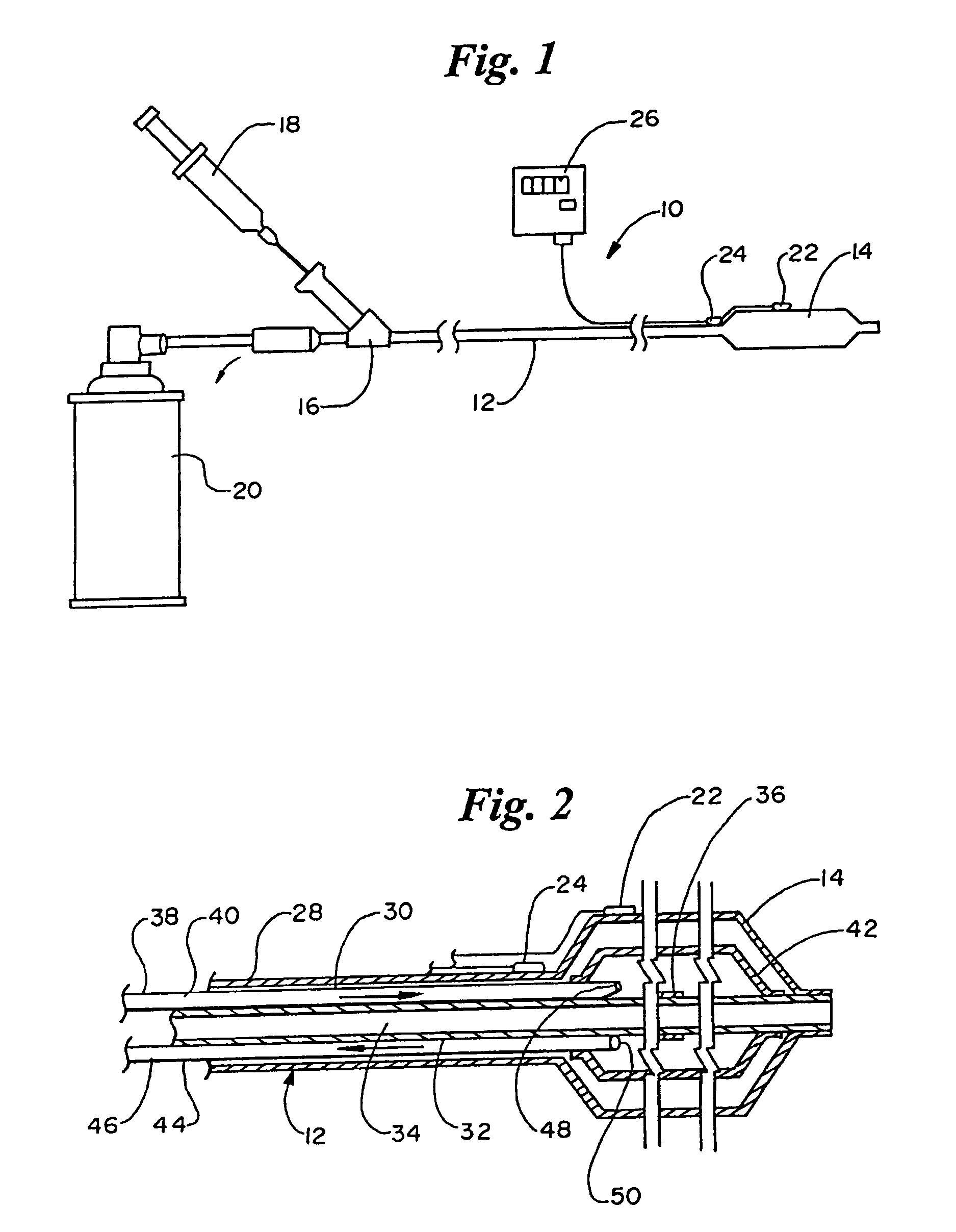
[0016]Referring now to the drawings wherein like reference numerals refer to like elements throughout the several views, FIG. 1 is a side view of a cryoplasty catheter 10 in accordance with the present invention. Shaft 12 has a proximal end and a distal end. A dilatation balloon 14 is disposed at the distal end of shaft 12. At the proximal end of shaft 12 is a manifold 16. Connected to manifold 16 is a pump 18, which can be hand pumped for inflating balloon 14. A coolant source 20 is also connected to manifold 16 which, as explained below, provides a supply of coolant to balloon 14. Catheter 10 can be provided with a thermo-resistive temperature sensor 22 for monitoring the temperature of a lesion and a thermo-resistive control sensor 24 connected to a monitor 26.

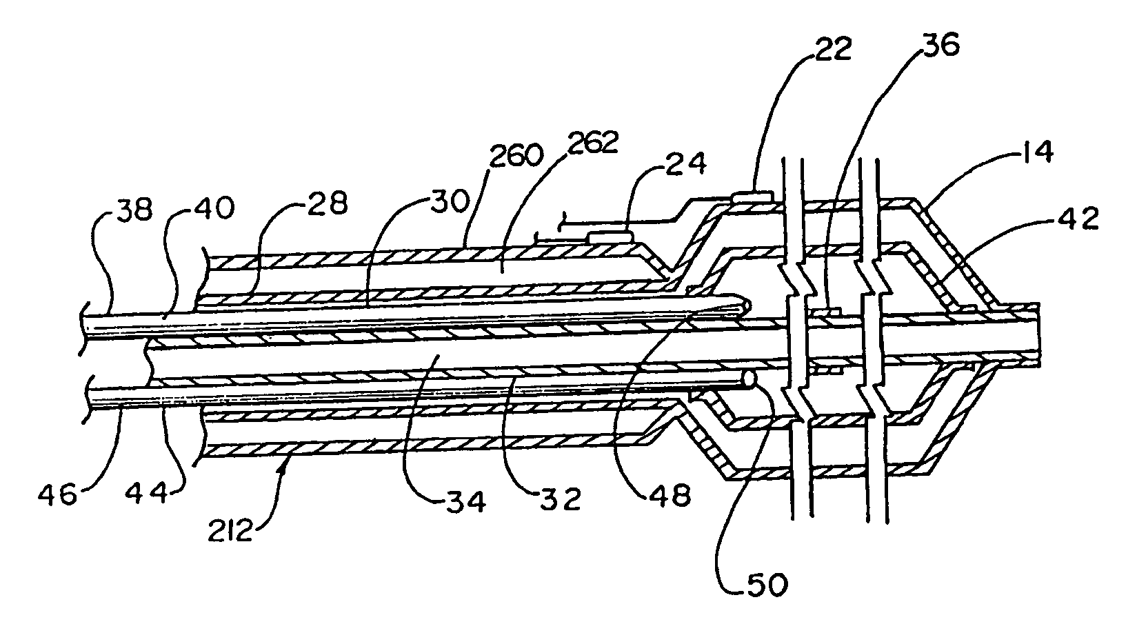
[0017]FIG. 2 is a longitudinal, cross-sectional view of the distal end of catheter 10 including the distal end of shaft 12 and balloon 14. Shaft 12 includes an outer tube 28 which defines an inflation lumen 30 in fluid comm...


PUM

PropertyMeasurementUnit
temperatureaaaaaaaaaa
diameteraaaaaaaaaa

Abstract

A cryoplasty catheter and method for preventing or slowing reclosure of a lesion following angioplasty. The cryoplasty catheter includes a shaft having proximal and distal ends and a dilatation balloon disposed at the distal end. An intake lumen and exhaust lumen are defined by the shaft to deliver coolant to the balloon and to exhaust or drain coolant from the balloon. The method in accordance with the present invention includes cooling a lesion to aid in remodeling the lesion through dilatation and / or freezing a portion of the lesion adjacent the dilatation balloon to kill cells within the lesion to prevent or retard restenosis.

Description

[0001]This is a continuation of application Ser. No. 09 / 916,147 as filed on Jul. 25, 2001 U.S. Pat. No. 6,648,878, which is a continuation of application Ser. No. 09 / 229,080 as filed on Jan. 12, 1999, now U.S. Pat. No. 6,290,696, which is a divisional of application Ser. No. 08 / 812,804 as filed on Mar. 6, 1997, now U.S. Pat. No. 5,868,735.FIELD OF THE INVENTION[0002]The present invention pertains generally to the field of angioplasty and, in particular, to a form of angioplasty involving lesion cooling.BACKGROUND OF THE INVENTION[0003]Conventional angioplasty has been preformed for several decades, prolonging the lives of an ever increasing number of patients. Angioplasty procedures involves the dilatation of a balloon placed across a lesion in a coronary artery. Dilatation of the balloon in turn dilates the lesion, opening the artery for increased blood flow. In some cases, however, the goal of the angioplasty procedure is, in whole or in part, frustrated by complete or partial rec...

Claims


Application Information

Patent Timeline
Patent Type & Authority Patents(United States)
IPC IPC(8): A61B18/18A61B17/00A61B17/22A61B18/00A61B18/02A61M29/02C21B13/00C22B5/14C22B23/02
CPCA61B18/02C22B23/021C21B13/0033C22B5/14A61B2017/00088A61B2017/00292A61B2017/00557A61B2017/22002A61B2018/0022A61B2018/0212A61M25/104A61B2018/00101
Inventor LAFONTAINE, DANIEL M.
Owner BOSTON SCI SCIMED INC
Why Eureka
Try Eureka